MIKE OPERATIONS tools
Introduction
This document focuses on how to develop MIKE OPERATIONS tools.
It assumes that the reader is familiar with programming against the MIKE OPERATIONS business layers. If this is not the case, the reader should first read and understand references /1/ and /2/.
What is a tool?
A MIKE OPERATIONS tool is a single-purpose component made available to the end-user through the MIKE OPERATIONS Tool Explorer. Single-purpose here implies that the tool focuses on a single action like resampling a time series or clipping a GIS feature set to a specified boundary. Since tools can be strung together into sequences in the Tools Explorer, more complex or multi-step actions can be handled this way and should not be developed as a single tool.
End-users typically access the tool through the MIKE OPERATIONS Tool Explorer as shown in the figure below.
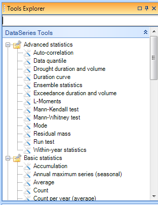
Figure 1 The Tools Explorer
A tool takes two types of input:
-
Input items which can be time series, GIS feature classes, spreadsheets, etc… In other words, items that often correspond to the basic MIKE OPERATIONS entity types.
-
Properties which are simple key-value type parameters that govern the processing. An example of a property could be the start date for processing a time series.
Input items are typically identified by an end-user by selecting one or more items in an Explorer or on a Data View. The user then selects the required tool in the Tool Explorer. The MIKE OPERATIONS framework automatically transfers the selected entities to the tool as input items. Properties are specified through the standard Property control.
Programming-wise input items are typically provided to the tool through its InputItems collection. The properties are standard .NET properties on the tool class itself.
From a software development point of view, a tool is simply a .NET class implementing the DHI.Solutions.Generic.ITool interface. ITool is a simple interface with just 7 members. It inherits itself from IToolDescription, ICloneable, ISelectable and IPlugin.
These interfaces are briefly described in the following table.
Table 1 Tool interfaces
| Interface | Description |
|---|---|
| ITool | Defines properties for getting input and output items, initializing the tool and executing it. |
| IToolDescription | Defines properties describing the tool and the input items it can operate on, including number and types of items. |
| ICloneable | Defines a method for cloning a tool instance. |
| ISelectable | A marker interface (without members) telling the system that a tool is selectable. |
| IPlugin | A marker interface (without members) telling the system that a tool is a DSS plugin. |
Only two items are required to implement a tool:
-
Make a .NET class that implements the 5 interfaces – of which 2 in fact are empty (marker interfaces).
-
Register the class with the MIKE OPERATIONS Runtime.config configuration file.
The MIKE OPERATIONS framework provides a base class that simplifies development of tools. This class provides a good deal of the necessary boilerplate code and thereby allows the developer to focus on the actual tool functionality.
Figure 2 shows a UML class diagram depicting the relationship of the classes and interfaces that are of interest when developing tools. The figure shows how a MyTool class generalises and realises implementation and interface classes.
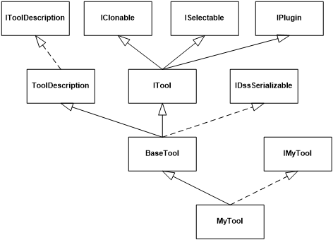
Figure 2 Tool UML class diagram
Note the following in the figure:
-
The MIKE OPERATIONS framework encourages developers to separate tool implementation into interfaces and implemented classes. This is the reason that the MyTool class has been made inheriting from IMyTool.
-
The BaseTool class provides implementation of all required interfaces – except the interface directly related to the functionality of the specific tool (IMyTool).
A walk-through - the Data Quantile tool
This section describes the required steps for implementing a specific tool – the Data Quantile tool - which calculates quantile values for one or more time series. Inputs to the tool are:
-
One or more time series
-
The fraction for which the quantile shall be calculated. The fraction is a value between 0 and 1.
Step 1 – Establish the Visual Studio solution
The first step involves creating a Visual Studio solution.
-
Start by creating a new Visual Studio solution - DataQuantile - of type Class Library.
-
Add references to the following assemblies:
Table 2 Assemblies referenced
| Assembly | Description |
|---|---|
| DHI.Generic.MikeZero.EUM | Functionality for item and unit conversion. |
| DHI.Solutions.Generic | Basic MIKE OPERATIONS framework functionality |
| DHI.Solutions.Generic.Tools | Basic MIKE OPERATIONS functionality related to tools |
| DHI.Solutions.TimeseriesManager.Interfaces | Time series management interfaces |
| DHI.Solutions.TimeseriesManager.Tools.Processing | Time series management processing functionality |
| DHI.Solutions.TimeseriesManager.Tools.TsUtilities | Time series management utility functionality |
| DHI.TimeSeries | DHI time series handling |
| DHI.TimeSeries.TsMath2 | DHI library for time series mathematics |
- Set the output path for the assembly to the folder where the MIKE OPERATIONS platform has been installed.
Step 2 - The IDataQuantile interface
Define an IDataQuantile interface as shown in the following listing.
Listing 1 IDataQuantile
Step 3 – Create and annotate the DataQuantile implementation class
Create the implementation class and add the class attributes as shown in the following listing.
Listing 2 DataQuantile class with attributes
Note the following:
-
The LocalizedXxxx attributes define the appearance of the tool in the Platform’s Toolbox component (see Figure 3 Tool property constants). These have been made localizable through the use of resources. A Resources.resx resource file will need to be added to the project and the text strings defined there using the resource names given in the attributes.
-
Tool_Category defines the name of the category under which the tool shall be placed in the Tool Explorer.
-
Tool_DisplayName holds the name of the tool as displayed in the Tool Explorer.
-
Tool_Description contains a description of the tool.
-
-
The SupportedType attribute defines the type of data the tool can operate on, which in this case is IDataSeries. IDataSeries is a key interface of the time series entities in the Time Series Manager. This attribute is used to ensure that the tool is only displayed in the Tool Explorer when the user has selected time series data.
-
The MinNoRequiredInputItems and MaxNoRequiredInputItems define the number of time series that the tool can operate on. In this case the tool can calculate the quantile for any number of time series.
-
The TypeOfOutput attribute defines the type of output provided by the tool. The output type here is a set of scalar values with the IScalar interface (see the section Output items and the table container below for further explanation).
Step 4 – Implement the IDataQuantile interface
Add the Fraction property from IDataQuantile to the DataQuantile class as shown in the following listing.
Listing 3 The Fraction property
Note the following:
-
The Fraction property has been annotated with three attributes. As with the class attributes, each of these have been made localizable through the use of resources defined in the Resources.resx file which has been added to the project.
-
Fraction_Category defines the category of the Fraction property under which it will be displayed in the Property Control.
-
Fraction_DisplayName holds the name of the Fraction property as displayed with the Property Control.
-
Fraction_Description holds the description of the Fraction property which is displayed at the bottom of property control when the Fraction property is selected.
-
The figure below shows the Visual Studio resource file and the MIKE OPERATIONS Tool Explorer and Property Control.
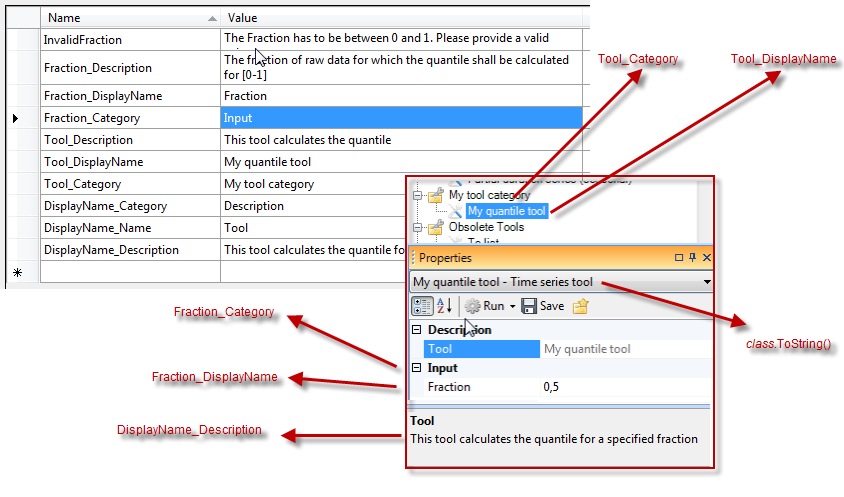
Figure 3 Tool property constants
-
_LockTool and _UnLockTool sets up a semaphore controlling access to the tool from multiple threads. The implementation of these methods are provided by the base class of the tool.
-
In case of invalid property values the tool shall throw a DssInputErrorException.
Step 5 – Implement the Clone method
Implement the ICloneable Clone method as shown in the following listing. ICloneable is an interface on the base class. This allows the tool and its properties to be copied. The method should return a copy of the tool with all defined properties and output items copied as shown in the listing below.
Listing 4 The Clone method
Step 6 – Implement the _ExecuteTool method
The key method in the ITool interface is the Execute method which—as the name implies—handles the actual tool execution. This method, however, is implemented by the BaseTool class by setting up event handlers, handling change log functionality and various initialisation and post-execution logic. The execution logic should therefore be added to the abstract BaseTool._ExecuteTool method which is called by the BaseTool.Execute method. This is done by overriding the _ExecuteTool method in the Data Quantile tool.
Note: Hints and best practices later in this section discusses in more detail the relationship between BaseTool and the class deriving from it.
Implement the _ExecuteTool method as shown in the following listing:
Listing 5 The _ExecuteTool
Note the following:
-
The method iterates over all input time series.
-
Here the data series is converted to the DHI time series object format. This is done because the quantile tool will use the DHI TS.Math library for the actual quantile calculation.
-
Here TS.Math calculates the quantile.
-
Then, the calculated quantile is moved from TS.Math to the local dataQuantile variable.
-
The quantile value is added to a table container which is the format used for returning output.
-
The table container is then added to the BaseTool’s output list.
-
Finally the output list is returned to the caller.
Step 7 – Registering the tool with the Runtime.config file
The last step involves adding the assembly information to the MIKE OPERATIONS’s Runtime.config configuration file. This file lists all the plugins that will be loaded when starting the application.
The entry for the Data Quantile tool is shown in Listing 6.
Listing 6 The runtime.config.entry
Note the following:
-
The DataQuantile tool is added to the CustomPlugins section in the runtime.config file.
-
The plugin description consists of three parts:
-
The class name including namespace of the tool, i.e. My.Tool.DataQuantile,
-
The plugin type which in this case is DHI.Solutions.Generic.ITool, and
-
The name of the assembly hosting the tool, e.g. My.Tool.dll
-
Figure 4 below shows the tool in the MIKE OPERATIONS Tool Explorer. Also, the listing below illustrates how it can be used from a Python script.
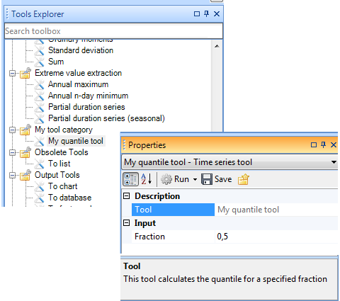
Figure 4 The data quantile tool in the Tool Explorer
Listing 7 Python script executing the tool
A custom user interface
As described in the previous section, the MIKE OPERATIONS standard property control handles the setting of tool properties. This is in most case adequate, but there may be cases where the tool developer needs to provide the user with a more elaborate input mechanism. UITools are a specialised version of the previously discussed ITool that support display of a custom tool user interface.
An example of such tool is displayed Figure 5.
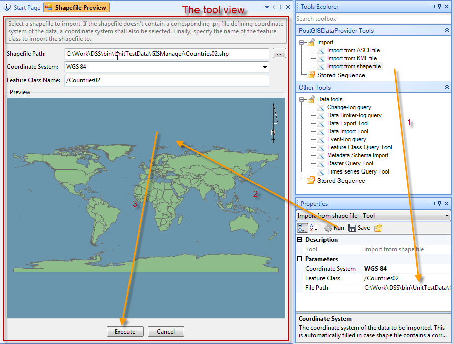
Figure 5 A UI tool
The figure shows the Shape File Import tool which makes use of a custom view for displaying a preview of the shape file that is being imported. The view is displayed when the user clicks the Run button in the Property control. In this case the actual tool execution happens when the user clicks the Execute button in the view.
A UITool is basically a combination of a standard tool, a MIKE OPERATIONS data view and a protocol for how the tool and view will communicate. You will need to implement two classes:
-
The view is a standard view derived from the .NET Form class and implementing the MIKE OPERATIONS IDataViewControl interface.
-
The tool is a .NET class implementing the IUITool interface. IUITool simply derives from ITool and IControl.
As was the case with simple tools, there is a base class for UITools that simplifies their development—BaseUITool. BaseUITool has the following important members
- Execute – which is the method called when the user clicks the Run button in the Property control. The basic processing in this method is illustrated in Listing 8.
Listing 8 BaseUITool.Execute
Execute calls UIExecute in the case where the AutoUIExecute property has been set to true and the tools has been provided with a reference to the application shell (the applications UI frame) otherwise it calls the base class’ (BaseTool) Execute method which ultimately calls the tool’s own _ExecuteTool method.
-
UIExecute – which is an abstract method that must be implemented by the tool itself. This method is responsible for displaying the tool’s view.
-
AutoUIExecute – which is a property that specifies whether Execute shall call the tool’s UIExecute method or the tool’s _ExecuteTool method (through the base class’ Execute method).
The relation between the classes handling UI tools are depicted in Figure 6
Figure 6 BaseUITool class relationships
Note from the figure how BaseUITool inherits the BaseTool implementation and implements the IUITool interface. IUITool has just two members—AutoUIExecute and UIExecute. IControl has a number of properties and an Initialize method that is called with a reference to the application’s shell object. The implementation in the tool will have to save this reference as a member variable for use when displaying the view.
The tool’s ExecuteUI method is responsible for showing the view. Listing 9 shows how this can be done.
Listing 9 How to display a tool view
Note how at (1) the view class is instantiated and at (2) is added to the shell’s collection of active views. At this point the view becomes visible. At (3) the tool removes any existing event handler and at (4) adds it for use while the view is open. The event handler, in this case the _DialogFinished method, will be called when the user dismisses the view.
Hints and best practices
This section provides more detail on different aspects related to the development of tools.
ITool and BaseTool
A tool, as described during the introduction, is simply a .NET class that implements the ITool interface. The ITool interface derives from a couple of other interfaces.
In order to simplify the development of tools, the MIKE OPERATIONS framework includes a base class, BaseTool, which the tool developer can inherit from. BaseTool provides implementation of all the ITool members listed in Table 3 below
Table 3 ITool members
| Interface | M/P/E | Member | Comments |
|---|---|---|---|
| ITool | M | void Execute | The main entry point for tool execution. |
| ITool | M | void Initialize | Initializes the tool. |
| ITool | P | bool CanExecute | Calls a virtual _CanExecute method for validating input items and properties. |
| ITool | P | IList\<object> InputItems | Holds the tools input items. The tool client adds items to this list. |
| ITool | P | IList\<object> OutputItems | Holds the tools output items. The tool client gets the output items from this list. |
| ITool | E | Executing | Event fired when execution starts. |
| ITool | E | Executed | Event fired when execution ends. |
The BaseTool class delegates the actual execution to an abstract method _ExecuteTool method with the following signature.
Listing 10 BaseTool._ExecuteTool
This method, which is called by the BaseTool.Execute method, shall be overwritten by the class deriving from BaseTool. The method shall return the tool output—one output element per input element.
ToolDescription
BaseTool derives from ToolDescription which implements IToolDescription. ToolDescription provides implementation for all of the IToolDescription members.
ToolDescription is a simple class providing the necessary implementation for describing tools in terms of:
-
Tool description, name and display name. The latter is for providing a localized name.
-
Minimum and maximum number of input items, for example, some time series tools can only operate on 2 input time series.
-
The type of items that the tool can operate on.
Note that the required description defined through IToolDescription and which is implemented in ToolDescription in fact is provided through .NET attributes as shown in Listing 11.
Listing 11 Attributes on a tool implementation class
The descriptions provided through the attributes are read by the tool when it is constructed, actually when the base class constructor in ToolDescription is called.
Output items and the TableContainer
The tool makes the output from an execution available as an OutputItems property on the tool. The definition of OutputItems is shown in Listing 12.
Listing 12 The OutputItems property
As can been seen from the declaration, OutputItems is just a list of .NET objects—typically one object per input item. The DataQuantile tool developed in the A walk-through - the Data Quantile tool section, returns the calculated quantile scalar values—which are of the .NET Double type—using the OutputItems list.
Different tools will have different output types which is the reason why ITool uses the generic object type as output type. For example, the standard ResampleTool provides time series as output items, i.e. a list of IDataSeries objects.
Most DHI supplied tools producing scalar values will in fact return a list of DHI.Solutions.Generic.Tools.TableContainer objects where a TableContainer is basically a wrapper around the standard .NET DataTable class. The reason for using TableContainer objects as output is to have a standardized way for clients to access output from scalar producing tools.
The classes and interfaces related to the TableContainer are shown in the following figure.
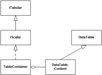
Figure 7 TableContainer class diagram
Clients pull data out of the TableContainer through its Rows property. As illustrated below in Listing 13 DHI supplied tools with scalar output will provide 3 output values per input item – the name of the input item, the actual calculated value and the unit of the calculated value.
Because of this, client code like Python scripts or custom C# code that interacts directly with tools will experience some complexity when pulling out the actual result from a tool execution through the list of returned TableContainer objects.
Listing 13 below demonstrates how to execute the DataQuantile tool from a standalone C# application and how to get the resulting quantile values out of the tool. The listing after that demonstrates how to execute a tool that produces a list of values instead of a single value.
Listing 13 Execute the Quantile tool from a C# client
Note the following in the listing:
-
The tool is retrieved from the Application object’s tool list. Note that the name of the tool must be the same as provided in the tool’s NameAttribute (see Listing 2 DataQuantile class with attributes).
-
A time series is fetched from the database.
-
The time series is added to the tool’s input items, the Fraction property set and the tool executed.
-
The TableContainer holding the results from the first input time series is returned. Note this execution has just one input time series which is why the OutputItems contains just one TableContainer.
-
The output is retrieved from the TableContainer. For tools producing scalar output, the TableContainer will contain three values—the name of the input time series, the calculated value, and the unit of the value.
Listing 14 Execute a time series producing tool
Note in the listing at (1) how the resample tool produces time series as output—and again if multiple input time series are fed to the tool the OutputItems will contain a time series for each input time series.
Property changed events
It is good practice to add property change notifications in the tool implementation. This makes it possible for components that hold references to the tool instance to be notified when other components change one or more of the properties.
Property change notification leverages the standard .NET PropertyChanged notification protocol, i.e.
-
The tool inherits from the INotifyPropertyChanged interface,
-
Provides a public PropertyChanged event, and
-
Implements a protected OnPropertyChanged(string propertyName) method that calls the delegates that have subscribed to the event.
This is illustrated in the Listing 15
Listing 15 Property change notification
The property notification handling happens through the bolded lines in the above listing.
-
The tool interface inherits from the .NET INotifyPropertyChanged interface.
-
The tool declares a public event of type PropertyChangedEventHandler.
-
The tool implements a method for firing events.
-
The tool calls the event-firing method.
Note: By convention, when multiple properties have changed, the event should be fired with an empty property name.
Locking a tool
A tool—or rather an instance of a tool—should protect itself from concurrent updates from multiple threads. The BaseTool class implements _LockTool() and _UnlockTool() methods that facilitates this protection. These methods shall be used when implementing the property getter and setter methods on a tool.
The pattern that should be followed when implementing properties is shown in Listing 16.
Listing 16 Locking and unlocking a tool when updating properties
Note in the listing how the setter locks the tool instance through a call to _LockTool before updating _myProperty and again unlocks the tool in the finally block.
The two lock methods synchronise access to the tool instance through the use of a .NET Monitor.
Runtime.config
The MIKE OPERATIONS Platform is highly configurable and can be extended in numerous ways. Although the Platform can be used as an application in and of itself, the primary purpose of it is to serve as a framework for making specialised applications by adding custom tools, job tasks, views, explorers, modules, and extensions to the user interface shell. All these custom components are called plugins—they plug in functionality to the Platform and thus provide the user with a useful application.
All the functionality provided by the Platform comes in the form of plugins which is why plugins are more than just custom-made components. They are in fact the basis of all the functionality that comes standard with the Platform or the application created on top of the Platform.
Plugins are loaded by the Platform based on their presence in the runtime.config configuration file which is located in the application’s installation folder. The only way to have a plugin loaded is to have it listed in the runtime.config file.
The overall structure of the runtime.config is as depicted in Figure 8.
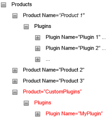
Figure 8 Runtime.config structure
Note from the figure:
-
Plugins are grouped into products, which typically equates to a Manager such as the Time Series Manager.
-
Each product can contain multiple plugins.
-
By convention all plugins not belonging to one of the standard managers should be placed under the CustomPlugins product node—as shown in red in the figure.
Each plugin is described through three parameters:
-
Name – This must be the fully qualified name of the .NET class implementing the plugin.
-
Type – This defines the type of plugin. The value must be the fully qualified name of the .NET interface that the plugin implements.
-
Assembly – This defines the assembly hosting the plugin. The value shall be the name of assembly file.
Table 4 below displays the possible basic plugin types. Note: the interface specified as Type in the runtime.config plugin definition shall match or inherit from one of these entries.
Table 4 Plugin types
| Plugin interface Type name | Description |
|---|---|
| DHI.Solutions.Generic.IDataViewControl | Designates a plugin that acts as a view |
| DHI.Solutions.Generic.IDTO | IDTO is strictly speaking not a plugin, but rather an identification of a class that holds mapping information between tables in the database and .NET classes |
| DHI.Solutions.Generic.IExplorerControl | Designates a plugin that shall act as an explorer |
| DHI.Solutions.Generic.IMenu | Designates a plugin that shall act as a menu |
| DHI.Solutions.Generic.IModule | Designates a plugin that shall act as a business layer module |
| DHI.Solutions.Generic.IPropertiesControl | Designates a plugin that shall act as a property control |
| DHI.Solutions.Generic.IShellExtension | Designates a plugin that shall act as a shell extension, i.e. extending the functionality of the Platform’s UI shell |
| DHI.Solutions.Generic.ITool | Designates a plugin that shall act as a tool |
| DHI.Solutions.Generic.IToolStrip | Designates a plugin that shall act as a tool strip |