MIKE OPERATIONS model adapters
Introduction
This document focuses on how to develop MIKE OPERATIONS model adapters.
The document will describe in detail, the steps to create an adapter for a simple model (inverted for the purpose), to be used within the MIKE OPERATIONS Platform.
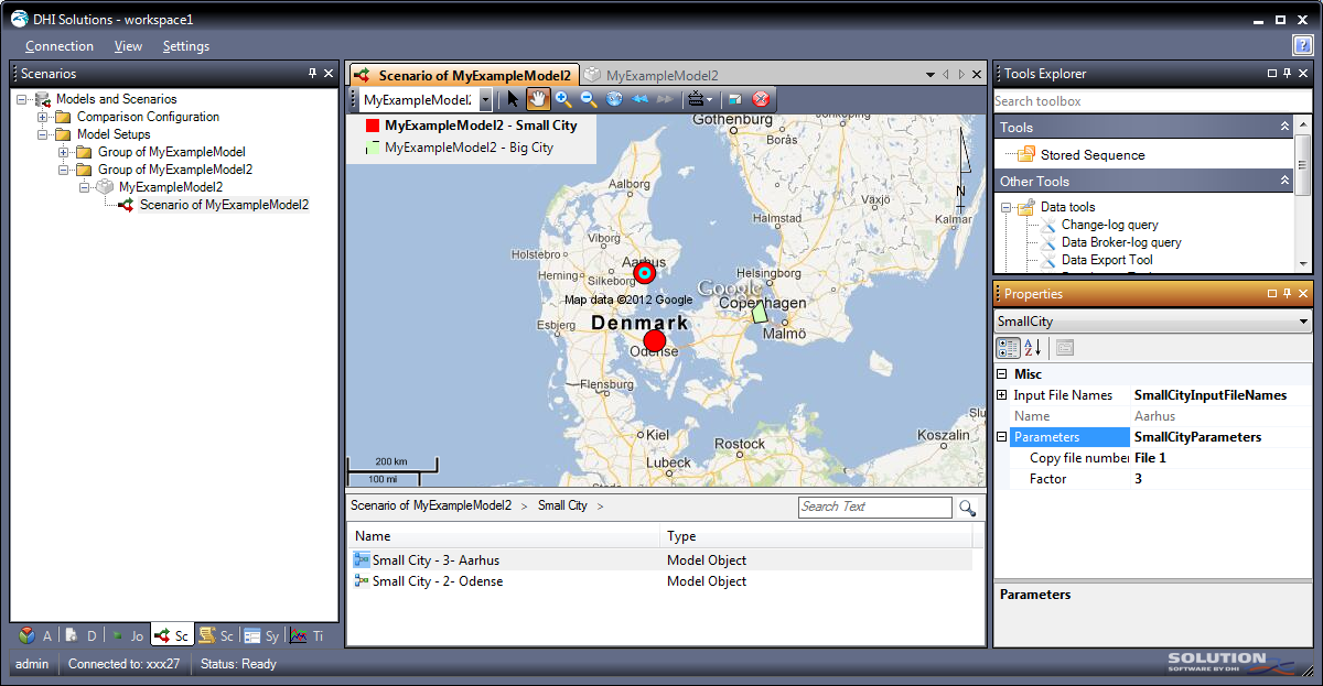
Figure 1: The example adapter for MyModel in the MIKE OPERATIONS Platform
The document assumes that the reader is familiar with programming against the MIKE OPERATIONS business layers. If this is not the case, the reader should first read and understand reference documents /1/ and /2/.
The reduce the amount of code listings in this document, it is accompanied with a zip-file containing the Visual Studio project, /3/
What is an adapter?
A MIKE OPERATIONS adapter is a component made available to the end-user through the MIKE OPERATIONS Scenario Manager. It wraps a numerical model in a generic format in MIKE OPERATIONS, allowing it to be used with other models (of the same and other modelling tools).
The adapter functionality is largely divided into two groups: configuration and runtime. The configuration adapter is used to define the model in the MIKE OPERATIONS database. The runtime adapter is used by MIKE OPERATIONS to execute the model with varying inputs – single run, ensemble runs or optimization. See reference document /3/ for further details on how to use the model from the MIKE OPERATIONS application.
An adapter must implement IAdapter interface which is a combination of IConfigurationAdapter and IRuntimeAdapter interfaces.
The MIKE OPERATIONS model concept
MIKE OPERATIONS uses a conceptual data model, consisting of a set of nodes (model objects). Each model object has input and output time series, parameters and can have additional outputs (binary data). The model can have other outputs (e.g. log files).
It is possible for a model setup to re-use input time series multiple times in a node as well as between nodes.
The model setup can have a geographic reference and the model objects can refer to a geographic feature (point, line, or polygon) in the coordinate system, allowing it to depict the schematic.
It is the job of the configuration adapter to translate the model definitions of the proprietary model setup and modelling tool into the MIKE OPERATIONS modelling concept.
From a software development point of view, an adapter tool is simply a .NET class implementing the DHI.Solutions.ScenarioManager.Interfaces.IAdapter (or IAdapter2 which is an extension of IAdapetr with an additional configuration method). Besides defining simple properties, this interface also inherits from IConfigurationAdapter and IRuntimeAdapter.
The interfaces are briefly introduced in Table 1.
| Interface | Description |
|---|---|
| IAdapter | Top level interface of an adapter – required to both configure and run an adapter |
| IAdapter2 | Same as IAdapter but extended with the ExportModel methods |
| IConfigurationAdapter | Interface for the configuration properties and methods of an adapter |
| IRuntimeAdapter | Interface for the runtime properties and methods of an adapter |
Table 1: Adapter interfaces
| Interface | Description |
|---|---|
| IAdapterHelper | Interface for a class to assist the adapter developer to create Platform defined classes |
| IDecisionValues | Interface used by Optimization, defining the decision variable details |
Table 2: Additional interfaces
To make and use an adapter the following is required:
-
Make a .NET class that implements the IAdapter interface
-
Register the class with the MIKE OPERATIONS Runtime.config configuration file.
The MIKE OPERATIONS framework provides a set of base classes that simplifies development of new adapters. These classes implement the basic properties of the interfaces thereby allowing the developer to focus on the actual adapter functionality.
Figure 2 provides a UML class diagram depicting the relationship of the classes and interfaces that are of interest when developing adapters. The figure shows how a MyExampleAdapterMyModel generalises and realises the implementation and interface classes.
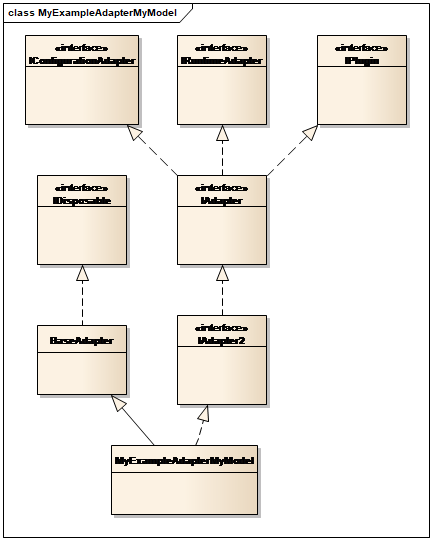
Figure 2: UML class diagram of MyExampleAdapterMyModel class
Note the following in the figure:
-
The BaseAdapter class provides implementation of some basic properties of the interfaces – except the interface directly related to the functionality of the specific tool.
-
The adapter is IDisposable (used for clean-up logic)
-
The adapter implements IPlugin (and empty interface), identifying it as a plug-in component in the Platform, see section 4.3 Runtime.config
Data series
Models usually work with time series data. MIKE models have proprietary format files to store such information and so do most model tools. The MIKE OPERATIONS works with IDataSeries for time series. It is the responsibility of the adapter to convert between dataseries and the internal model representation.
During configuration the adapter will return samples of the model input time series and at runtime the adapter will get dataseries of new data for the model run and return output time series from the simulation result.
The exchange format is in the form of IDataSeries, hence the adapter must know the IDataseries interface to operate the class. In order to enable the adapter to create such a series, the AdapterHelper contains a method which returns an empty DataSeries object for the adapter to fill.
Section 4 Hints and best practices describes a way to reduce memory footprint and return data series on demand.
Model Object concept
Each model node in the setup can have parameters. A parameter can be supplied to the system for information (e.g. the name or type of the node, the location of the node) or it can be possible to change the value of the parameter in the system and return it to the adapter at runtime for update of the model setup.
The adapter defines the parameters of a node, their name, type and value and provides them to MIKE OPERATIONS during configuration. The information provided must be sufficient for MIKE OPERATIONS to display, modify and validate them so that they can be returned to the adapter at runtime in a valid and understandable form.
The exchange of information is in the form of XML and XML schema (XSD). The adapter defines the XML Schema to describe a model node parameter – also called a model object and for the particular model node the XML describing the actual parameters is created.
Use of simple XML and XSD is possible, but it offers only little possibility for the adapter to define the validation and description of the model object parameters required for a user-friendly system. Hence, classes exist in DHI.Solutions.Generic namespace giving a set of data types to be used to define parameters (Boolean, Datetime, Integer, Double, String, Tabular) which have additional properties to provide references to resources in the adapter as well as upper/lower range or list validation of values. These types are also expressed in Baseschema.xsd which can be used in schema validation in Visual Studio when defining the model object schema.
The _parseModel section gives an example of how a simple model object can be constructed.
The 4 Hints and best practices section describes the procedure for defining model objects as well as getting a copy of the BaseSchema.xsd
GIS data and symbology
The adapter can return geographical information (feature details) for the model node (or model objects) allowing the Platform to construct layers with the GIS Manager for each model object type. The default symbology to be used for displaying the nodes on a map can also be specified.
The 4 Hints and best practices section describes how to deal with GIS details.
Running a scenario
The Scenario Manager can use the adapter to run the model in different ways:
-
Single model run - the single model is a special case of ensemble simulations, i.e. the adapter is called the same way as in point 3 below.
-
Linked models - the Scenario Manager will sequentially call the adapters controlling the sequence of model setups, with each adapter being treated as a single model run as in point 1 above.
-
Ensemble runs – In an attempt to improve speed and utilize multi-core processors, the Scenario Manager will start multiple threads of single model runs. In order to distribute this work, multiple adapters are started for the same model setup, each by calling:
-
the IRuntimeAdapter.PreProcess method followed by
-
the IRuntimeAdapter.Run method with the flag indicating PreProcessing is not to be carried out. And finally
-
The Dispose method to clear memory and release the adapter object.
-
Optimization run - in this situation the Scenario Manager will prepare the initial setup, update the input after each model execution and extraction of results several times in a loop and the final clean-up is only carried out once the run is complete. For the Optimization run, the calls are:
-
IRuntimeAdapter.PreProcess
-
IRuntimeAdapter.RunEnginePrepare
-
Optimization loop:
-
IRuntimeAdapter.OverwriteInput
-
IRuntimeAdapter.RunEngine
-
IRuntimeAdapter.RetrieveOutputs
-
-
RuntimeAdapter.Dispose
For this reason the adapter should implement different methods (some which actually use the other):
-
Run
-
PreProcess
-
RunModel
-
RunEnginePrepare
-
RunEngine
-
RunEngineFinish
-
-
RetrieveOutputs
The transfer objects
Data is transferred between the adapter and the Platform using transfer objects. The adapter has three main properties for this purpose, being:
-
AdapterModelSetup – for transferring model setup configuration data from the adapter to the Platform
-
AdapterSimulationInput – for transferring simulation data (model setup copy, input variations, run details) from the Platform to the adapter
-
AdapterSimulationOutput – for transferring simulation outputs (new initial conditions, time series, logs etc) from the adapter to the Platform.
Each of these objects contain properties and lists of other objects which together make up a data structure of data to transfer – which closely resembles that of the platform for holding model setup, scenario and simulation. These are listed in Table 3 to Table 5 below.
The transfer objects are defined by interfaces and namespace DHI.Solutions.Adapters has a default implementation of these interfaces.
| Interface | Description |
|---|---|
| IAdapterModelSetup | Top level properties for configuration data transfer objects |
| IAdapterModelSetupInitialCondition | Definition of (a set of) file(s) which make up a model state |
| IAdapterModelSetupInitialConditionList | List of initial conditions |
| IAdapterModelSetupInputTimeseries | Definition of a time series input to the model setup in a node. |
| IAdapterModelSetupInputTimeseriesList | List of initial conditions |
| IAdapterModelSetupModelObject | Definition of a model object node – with name, geographic location and a parameter object definition. Also has a list of input and output time series. |
| IAdapterModelSetupModelObjectList | List of model object nodes |
| IAdapterModelSetupOtherOutput | Definition of a piece of output data – type given by mime-type. Typically log files. |
| IAdapterModelSetupOtherOutputList | List of model outputs |
| IAdapterModelSetupOutputData | Definition of a piece of output data – associated to a model object node. Type given by mime-type. |
| IAdapterModelSetupOutputDataList | List of output data for nodes |
| IAdapterModelSetupOutputTimeseries | Definition of an output time series – with name, geographic location. |
| IAdapterModelSetupOutputTimeseriesList | List of output time series |
Table 3: Adapter data interfaces for configuration under AdapterModelSetup property
| Interface | Description |
|---|---|
| IAdapterSimulationInput | The simulation input (includes the model setup content) |
| IAdapterSimulationInputInitialCondition | The initial condition to start the model from |
| IAdapterSimulationInputTimeseries | Definition of an input time series (reference and data) |
| IAdapterSimulationInputTimeseriesList | List of input time series |
| IAdapterSimulationModelObject | Definition of model object variation (reference and eventual modified model object parameters) |
| IAdapterSimulationModelObjectList | List of model objects |
| IAdapterSimulationOtherOutput | Definition of requested other output (reference) |
| IAdapterSimulationOtherOutputList | List of output definitions |
| IAdapterSimulationOutputData | Definition of requested output (reference) |
| IAdapterSimulationOutputDataList | List of output data definitions |
| IAdapterSimulationOutputTimeseries | Definition of requested output time series (reference) |
| IAdapterSimulationOutputTimeseriesList | List of requested output time series |
Table 4: Adapter data interfaces for simulation input
| Interface | Description |
|---|---|
| IAdapterSimulationOutput | Definition of the simulation output returned by the adapter (includes initial conditions) |
| IAdapterSimulationOutputInitialCondition | Definition of the output initial condition (data and timespan) |
| IAdapterSimulationOutputOtherOutput | Definition of returned other output |
| IAdapterSimulationOutputOtherOutputList | List of returned other output |
| IAdapterSimulationOutputOutputData | Definition of returned output data |
| IAdapterSimulationOutputOutputDataList | List of returned data |
| IAdapterSimulationOutputOutputTimeseries | Definition of returned output time series |
| IAdapterSimulationOutputOutputTimeseriesList | List of returned output time series |
Table 5: Adapter data interfaces for simulation output
A walk-through
This section describes the steps for implementing a specific adapter – the MyExampleAdapterMyModel adapter - which wraps a very simple calculation model to exemplify the adapter concept.
The example model
The example model is defined for the purpose. You can copy a time series and multiply the values in it with a factor.
The model tool is a bat-file MyModel.bat and a VBScript, MyModel.vbs, which both reside in the model setup folder. The VBScript defines the configuration file to always be named MyExample.csv. It is a comma separated configuration file which may look like this (4 lines):
ID;Name;Type;Input1;Input2;Input3;Output;CopyFileNo;Factor;Geometry
1;Copenhagen;Big
City;FILE1.dfs0;FILE2.dfs0;FILE3.dfs0;output1.dfs0;1;1;POLYGON((12.55
55.86,12.35 55.74,12.41 55.60,12.67 55.62,12.55 55.86))
2;Odense;Small
City;FILE1.dfs0;FILE3.dfs0;FILE3.dfs0;output2.dfs0;1;2;POINT(10.42 55.40)
3;Aarhus;Small
City;FILE2.dfs0;FILE3.dfs0;FILE4.dfs0;output3.dfs0;1;3;POINT(10.22 56.16)
The configuration file defines a number of nodes – one for each line. It has the following structure:
Each node has three input time series and one output time series. A parameter, CopyFile defines which input time series is to be copied to the output time series. Time series are dfs0-files. Another parameter, Factor gives a number with which to multiply all the values in the time series.
Geometry is the Well Known text for polygon and point respectively. The model uses (hardcoded) projection WGS 84 so the coordinates in the Well Known Text are Latitude and longitude.
The types of nodes are:
-
Big City, identified with a name and a polygon
-
Small City, identified with a name and a point
If Parameter is 1, 2 or 3 time series input1, input2 or Input3 respectively will be copied to output and multiplied with the value of Factor.
This setup illustrates that:
-
Nodes exist with different types and geometries
-
Input time can be used multiple times in a node
-
Input time series can be used multiple times between nodes
-
Model objects can have read-only and changeable parameters of different types. The adapter code will further show how value of changeable parameters can be limited to lists or ranges.
-
The setup is run by executing the bat-file. It will generate a log-file called MyModel.log
Step 1 – Establish the Visual Studio solution
The first step involves creating a Visual Studio solution for the development.
-
Start by creating a new Visual Studio solution - MyExampleAdapter - of type Class library.
-
Add references to the following assemblies as shown in Table 6.
-
Set the output path for the assembly to the folder where the MIKE OPERATIONS platform has been installed.
| Assembly | Description |
|---|---|
| DHI.Solutions.ScenarioManager.Interfaces | Scenario management interfaces |
| DHI.Solutions.Adapters | Base adapter classes |
| DHI.Solutions.Generic | Access to helper classes to create model objects |
| DHI.Solutions.TimeseriesManager.Tools.ImportTools | Tool to import dataseries from dfs0-files |
| DHI.Solutions.TimeseriesManager.Tools.TimeseriesExportTool | Tool to export data series to dfs0 |
Table 6: Assemblies referenced
Step 2 – Class construction and the IAdapter2 interface
Rename the MyExampleAdapter.cs file (and thus the corresponding class) to MyExampleAdapterMyModel.cs as you need to have a different namespace and class name (see Step 3 – Configuration adapter below). Alternatively change the namespace. The class shall implement the IAdapter2 interface shown in the following listing:
Listing 1 Class definition
Inheriting the BaseAdapter will provide direct implementation of properties ID and Name which just need to be initialized.
Right-click the IAdapter interface and choose to implement the interface. It will generate all the properties, methods and events the adapter must implement to meet the requirements of MIKE OPERATIONS.
NB: make sure the namespace and the class have different names. Otherwise the model object logic may not work.
Make a constructor
Use the constructor to define the name and unique class id of the adapter. The SupportedModelTools holds a list of the names of the modelling tools supported by the adapter.
Listing 2 Constructor
Add a resource file
Strings and other resources can conveniently be kept in a resource file so you should add this to the project. Call it MyExampleAdapterResource. It is already being used in the constructor for holding the AdapterName string.
When dealing with model objects later it becomes important that this resource manager is public. Each time it is being edited, Visual Studio will change the access modifier to internal and this has to be changed in the c# code manually as highlighted with yellow in Listing 3.
Listing 3 Changing the access modifier of the resource manager
Step 3 – Configuration adapter
The aim of the Configuration adapter is to:
-
Provide detailed information for the Platform to represent the model setup, allowing it to be recreated in a different location and run without changes, incorporating the following:
-
Input time series including data
-
List of outputs
-
Time series
-
Other data
-
-
Model objects including links to input and outputs and optionally with
-
GIS data
-
Model object parameters
-
-
A zip (or similar) data (files).
-
Record a link between information provided to the Platform and the location in the model setup (in order to be able to update the setup with a new version of the provided information at runtime).
Make AdapterHelper property
The AdapterHelper property is there for the system to provide a call-back option to the application and additional helper classes. It is assigned by the system, so the adapter only needs to know the interface.
Listing 4 AdapterHelper property
Make AdapterModelSetup property
During configuration the adapter must fill a property of type IAdapterModelSetup. The system only accesses this by interface. Standard classes are defined in namespace DHI.Solutions.Adapters, but the adapter may need to implement the interface by its own class – for instance by inheriting.
Listing 5 Making a local variable to the AdapterModelSetup
Listing 6 AdapterModelSetup property
The class (and other classes of the so-called Transfer Objects) is defined in sub-folder TransferObjects.
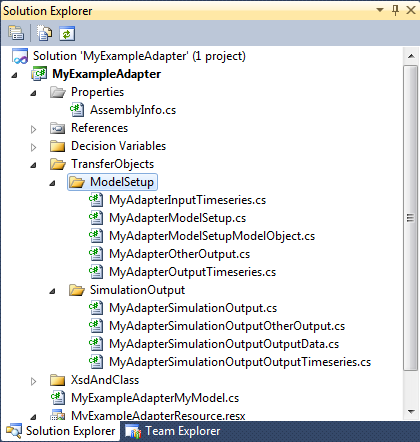
Figure 3: The Data Transfer Objects in the adapter
The class inherits from the base class DHI.Solutions.Adapters.AdapterModelSetup, which has a base implementation of the interface. This new class will further implement the GetContent method to return the necessary files in zipped form. Note the BaseAdapter.ZipFiles is used for this purpose.
A couple of properties have been added to the class to allow the adapter to populate it with information of the files and folders to zip.
Listing 7 MyAdapterModelSetup class
Make CanConfigure property
This property will inform the system whether the adapter can be used to configure a model setup. It can be used to perform license checks or check if the required prerequisites are installed. In this example we simply return true.
Listing 8 CanConfigure property
Make internal classes for model object types
Before continuing with the configuration methods, you need to define some helper classes which can hold information about the model object types and their XML schema.
Listing 9 ModelObjectType helper class
The class ModelObjectType simply defines the type with Id, Name, Description and XMLSchema. The Id should be a hard coded value unique for the type.
The ModelObjectTypeList class is a static class which holds a list of the defined model object types, making I searchable.
Listing 10 ModelObjectTypeList helper class
Make GetModelObjectSchema method
This method shall return the schema for the model object type passed. We do that by searching the list with the type Id.
Listing 11 GetModelObjectType method
Make GetModelObjectTypeName method
Listing 12 GetModelObjectName method
The GetModelObjecTypeName is similar to GetModelOjectSchema but will return another property.
Make GetSymbology methods
The Scenario Manager displays the features of the model object nodes in the model setup on a map. For this use it needs to ask the adapter for the symbology to use for the features.
The symbology is expressed as a XML string.
(See GIS data and symbology in section 4.2).
).
Listing 13 GetSymbology method
The implementation for the MyExampleAdapter will return symbology for Small City model objects as a solid red circle of size 20, while the Big City model object are represented by a green polygon with a black edge.
The translation into symbology XML happens in private method _GetSymbolDocument, see next code Listing 14.
Listing 14 GetSymbolDocument private method
Make GetResourceManagerType method
Although defined as part of the IRuntimeAdapter interface, this method is also used by the configuration process, for instance to get the XML Schema information of the model objects and the display properties of the adapter.
It will return a reference to the resources of the adapter DLL.
Listing 15 GetResourceManagerType method
Make Configure method
The configure method is the main entry during configuration. It shall populate the data structure of AdapterModelSetup property of the adapter.
The method checks if the adapter can configure (this has probably also been done by MIKE OPERATIONS before calling Configure), then it will ask you to select a csv-file and following the successful return of a file, it will start the configuration by setting the RoofolderPath and calling three private methods which will parse the setup and retrieve the details and populate the adapter with configuration information.
Setting the RootFolderPath here is done because the adapter in this case assumes that the CSV-file is in the root of the setup and that files are located ‘below’ that folder. Other modelling tools may have different rules and the logic of the adapter must reflect that.
MIKE OPERATIONS does not assume anything about folders and files, so the adapter must handle it.
Listing 16 Configure method
_getProjection
The private method _getProjection will simply set the projection of the model setup. In this example the projection is hard-coded to the Well-Known-Text format of the WGS 84 coordinate system of latitude and longitude.
Listing 17 _getProjection private method
_parseModel
The _parseModel private method will, through a couple of other private methods, read the csv-file and express the details in MIKE OPERATIONS terms.
Listing 18 _parseModel private method
Due to the simplicity of the setup, parsing of a “Big City” and a “Small City” is the same except for the type, hence the first two methods are completely parallel (simply replace Big with Small in the code).
Listing 19 _getCityNodes private method
The method loads the CSV-file data, splits it into lines, loops over the lines and finds the lines for the specified type of City – and eventually calls a method to handle configuration of a single node.
The node is represented by IAdapterModelSetupModelObject implemented by MyAdapterModelSetupModelObject which is inherited from the base AdapterModelSetup class as you need an additional property CsvId to identify the model object location in the csv-file. The node should have a unique name and the feature is in the form of a string in Well Known Text format (as is our csv-file detail).
The AdapterReferenceId is important as it is a token used in the communication between MIKE OPERATIONS and the adapter, identifying the model object at runtime. Each model object must have a unique id.
Listing 20 _makeBigCity private method - creating the model object (1/9)
The next 9 listings show how the BigCity class we have defined for the model object parameters is populated with details. Common for them are properties like DisplayName (giving a resource name in the resource manager of the adapter or the test to display in case the resource is not present), Read-only (defining if the property can be changed) and Value (giving the value of the parameter).
First, the read-only Name of type String:
Listing 21 _ makeBigCity private method – creating the model object parameters and assigning the name (2/9)
Parameters CopyFile and Factor reside in a section called Parameters. We need to create that.
Listing 22 _ makeBigCity private method – creating the Parameters section (2/9)
The next parameter, CopyFile, is an integer (1, 2 or 3) indicating the file to copy. It is non read-only, i.e. it can be changed by the user in the Scenario Manager. You want to limit the value to the possible choices, as a filename may be blank in the csv-file and therefore invalid. This is achieved by populating the List property of the Integer with name (or Key) and Value to a display string representing the key. Both key and value are strings. It is important that the key can be converted from string into a valid value of CopyFile, i.e. integer.
Listing 23_ makeBigCity private method – creating the CopyFile Integer with list (3/9)
The Factor parameter is of type Float. It is non read-only and the value is converted from the text of the csv-file field. This example limits the allowed interval for the Factor to a range from -5 (inclusive) to 5 (exclusive).
Listing 24 _ makeBigCity private method – creating the Factor Float with range (4/9)
Next are three read-only properties showing the input file names of the configuration. They are grouped into the InputFileNames section which we create first:
Listing 25 _ makeBigCity private method – creating the InputFileNames section (5/9)
Listing 26 _ makeBigCity private method – creating read-only filename strings (6/10)
Finally, the XML defining the parameter model object parameters is created by serializing the BigCity object and assigning it to the AdapterModelObject. See the _serialize method in a later listing.
Listing 27 _ makeBigCity private method – making the parameter XML (7/10)
When you are done with the parameters, each of the input time series of the nodes must be expressed explicitly by adding definitions for them to the AdapterModelObject.ModelInputTimeseriesList. You loop over the three possible filenames and if the name is not blank you create a MyAdaperModelInputTimeseries and assign it to the list of time series for the model object. Creation of the object is done by private method _addFileAsInput (see later listing).
Listing 28 _ makeBigCity private method – adding input time series (8/10)
The same concept exists for output time series, except the adapter only needs to return a definition of a potential output time series and not the time series data itself.
Listing 29 _ makeBigCity private method – creating the output timeseries (9/10)
Now complete the model object must be added to the list of model object in the model setup.
Listing 30 _makeBigCity private method – adding the model object to the adapter (10/10)
The model object XML is created by serializing the instances of BigCity and SmallCity objects using a serialization method like shown below.
Listing 31 _seriealize private method
The _addFileAsInput method takes 3 arguments – the name of the file as it is in the csv-file, the ID of the line in the CSV-file and the number of the input file (1, 2, or 3).
You need to check if the input time series has been referred to before, as the model setup should only return the time series once at configuration time. If you do not ensure uniqueness MIKE OPERATIONS will consider the file reference to be different time series and may return multiple DataSeries which will refer the same time series file and the adapter will then have problems deciding which time series to use.
The class MyAdapterModelSetupInputTimeseries is created and populated with the details – and the Timeseries property defined will return the IDataSeries on demand. See section The custom transfer objects.
Listing 32 _addFileAsInput private method
The_addFileAsOutput makes a reference to the output time series file of the node using the MyAdapterModelSetupOutputTimeseries to store the filename and the node ID.
Listing 33 _addFileAsOutput private method
_prepareForRegistration
This method will perform the final touch on the configuration information. This means making an adapter configuration file holding the various adapter reference ids with their respective details, making it possible to find the node in the csv-file at runtime, listing of all the files to zip and populating the MyAdapterModelSetup with it all.
Listing 34 _prepareforRegistration private method
This adapter configuration file is finally included in the model setup file list, so the system ensures the file is present at the same relative location at runtime.
The custom transfer objects
As mentioned, a couple of classes are created to hold the configuration information needed in addition to the details required by Scenario Manager. These are as follows:
-
MyAdapterModelSetupInputTimeseries – inherits from DHI.Solutions.Adapters.AdapterInputTimeseries, adds properties of NodeID, InputID and FileLocation describing the configuration details of the file and implements a method to return the dataseries in Timeseries property on demand
-
MyAdapterModelSetup – inherits from DHI.Solutions.Adapters.AdapterModelSetup, adds properties of files and folders to zip and implements GetContent to zip the files
-
MyAdapterModelSetupModelObject – inherits from DHI.Solutions.Adapters.AdapterModelSetupModelObject, adds property CsvId to hold a reference to the line in the csv-file
-
MyAdapterModelSetupOutputTimeseries – inherits from DHI.Solutions.Adapters.AdapterOutputTimeseries, adds properties of NodeID and FileLocation describing the configuration details of the file.
-
MyAdapterModelSetupOtherOutput – inherits from DHI.Solutions.Adapters.AdapterModelSetupOtherOutput, adds property FileLocation describing the location of the output file.
MyAdapterModelSetupInputTimeseries is the most interesting, as it shows how to implement the On-demand loading of data series. In this case, a time series tool from the TimeSeries Manager has been utilized as it encapsulates the dfs0-file and makes the code simple.
The other classes simply have the additional properties to carry the information from _parseModel to _prepareForRegistration logic so the MyAdapter.cfg configuration file can be created.
The tool is included through a reference to DHI.Solutions.TimeseriesManager.Tools.ImportTools and the class then needs:
-
References to DLLs
-
a constructor using AdapterHelper
-
a Timeseries property override
-
the private methods _ReadTimeseries
This method will use ImportFromDfs0 time series tool to read the dfs0-file into a data series.
Make EditModel method
The Edit model is used by the “Open in native model tool” menu option in Scenario Manager. The intention is that the adapter will unpack the model setup content such that it gives a valid setup. The Scenario Manager does not assume anything about the location and type of the model setup content, but leaves it up to the adapter to do it.
The method is called from the UI and the implementation can make use of UI elements.
This example implementation simply unzips the content (as the adapter knows it was created using Zip) in a temporary folder and opens Windows Explorer on the folder.
Listing 35 EditModel public method
Make ExportModel method
ExportModel is added to IAdapter2 as an extension to IAdapter. The implemented method is similar to EditModel, but this time the location to export to is provided by the Scenario Manager assuming the model setup is file based.
Listing 36 ExportModel public method
The method simply creates the folder and unzips the model setup content.
Step 4 – Runtime adapter
AdapterSimulationInput property
This property reflects an object filled by Scenario Manager but initialized by the adapter. The adapter only needs to access the details of this data structure by interface.
Listing 37 AdapterSimulationInput public property
AdapterSimulationOutput property
This property reflects the data structure to be returned from the adapter after a simulation. A standard implementation exists, but usually it needs to be overridden (in this case in MyAdapterSimulationOutput ) as we need to be able to return a zipped structure of the simulation folder with GetContent method.
Listing 38 AdapterSimulationOutput public property
The implementation of the class is similar to that of MyAdapterModelSetup, with Files to be zipped.
MaxConcurrentRuns property
This property is related to ensemble simulations and informs MIKE OPERATIONS if the adapter can be instantiated multiple times in the same processor.
Listing 39 MaxConcurrentRuns public property
CanRun method
This method is similar to CanConfigure and can be used to check installation and licenses of the modeling tool before starting the runtime adapter.
Listing 40 CanRun public method
PreProcess method
This method shall establish the model setup from the model setup content and other inputs provided by the Scenario Manager in the AdapterModelSetup property.
Listing 41 PreProcess public property
This implementation uses a set of private methods to perform different parts of the task:
-
_prepareFolder will create a temporary folder and unzip the model setup content or use the root folder passed, in case the setup has be “checked out” on disk.
-
_prepareConfiguration will read content of the MyAdapter.cfg file into memory and from this information, extract the name of the csv-file with the model setup configuration. It will also read the csv-file content into memory.
-
_prepareInputTimeseries will loop over the input time series from MIKE OPERATIONS, match the AdapterReferenceId with the configuration information and write the content into the corresponding input file (using another time series tool).
-
_prepareModelSetup will loop over the model objects from MIKE OPERATIONS, match the AdapterReferenceId with the configuration information and use the NodeID to locate the line in the CSV-file. By doing this, it will extract the model object parameters (Factor and CopyFile) and update the csv-file.
Listing 42 _prepareFolder private method
Listing 43 _prepareConfiguration private method
Listing 44 _prepareInputTimeseries private method
The _writeInputTimeseries method eventually uses a Time Series Manager tool to convert the DataSeries to a dfs0-file.
Listing 45 _prepareModelSetup private method
If the simulation input model object contains XML, the parameters have been modified by the Platform and you must update the model setup accordingly. In this case, the CopyFile and Factor parameters must be written back to the csv-file. This is handled by the _setCityParameters. This method is internal as it is also being used by the methods called during the Optimization run.
_setCityParameters will do the following:
-
loop the configuration file data,
-
locate the model object definition by AdapterReferenceId and not the csf-file ID
-
loop the csv-file content to find the corresponding line
-
get the new values for Factor and CopyFile from the model object
-
update the csv-file content and save the file
Getting the parameters out of the model object is isolated in private method _getModelObjectParameters. This method uses _deserialize to establish the model object from XML and Xsd (matching the ModelObjectTypeId).
Listing 46 _setCityParameters internal method
Listing 47 _getModelObjectParameters private method
Listing 48 _desrialize internal method
Run method
The run method exists in 3 versions – which eventually end up in the same:-
Listing 49 Run public method – the two simple versions
Adapter delegates are methods that call or ‘hook’ into the adapter, which allows the caller to execute logic in addition to that of the adapter, see section AdapterDelegates.
The flag “preprocess” tells the Run method whether to execute preprocessing or not. If false, the PreProcess method is assumed to have been called before.
Listing 50 Run public method
RunModel
The RunModel method assumes PreProcess is complete and does what is required to execute the modeling tool and leave data ready for RetrieveOutputs.
Listing 51 RunModel public method
RunEnginePrepare
For this model, the RunEnginePrepare does nothing. However, for a model working with initial conditions, this could be the place to set/reset them before starting the engine.
Listing 52 RunEnginePrepare public method
RunEngine
For this model the RunEngine methods only call a private method which executes the bat-file.
Listing 53 RunEngine public method
Listing 54 runLaunchCmd private method
RunEngineFinish
For this model the RunEngineFinish does nothing. However, for a model working with initial conditions this could be the place to release any locks set by the engine.
Listing 55 RunEngineFinish public method
RetrieveOutputs
RetrieveOutputs shall populate the adapter with simulation outputs in AdapterSimulationOutput as requested by the system in AdapterSimulationInput.
In order to reduce the memory footprint and only get the time series on demand, a set of classes inherited from DHI.Solution.Adapters classes have been created – following the same principles as for AdapterModelSetup classes. They are as follows:
-
MyAdapterSimulationOutput – inherits from DHI.Solutions.Adapters.AdapterSimulationOutput, adds properties of files and folders to zip and implements GetContent to zip the files
-
MyAdapterSimulationOutputOutputTimeseries – inherits from DHI.Solutions.Adapters.AdapterSimulationOutputOutputTimeseries, adds properties of NodeID, InputID and FileLocation describing the configuration details of the file and implements a method to return the dataseries in Timeseries property on demand
-
MyAdapterSimulationOutputOtherOutput – inherits from DHI.Solutions.Adapters.AdapterSimulationOutputOtherOutput, adds property FileLocation describing the location of the output file.
These custom transfer objects are defined in sub-folder TransferObjects\SimulationOutput in the Visual Studio solution.
The method _readSimulationOutputTimeseries shows how the MyAdapterSimulationOutputOutputTimeseries is initialized.
Listing 56 RetrieveOutputs public method
Listing 57 _readSimulationOutputTimeseries public method
OverwriteInput
OverwriteInput is used by the system during optimization simulations to set selected parameters and/or input time series to new values. How this is done will vary greatly from modeling tool to modeling tool.
The system will provide data from the optimizer in the form of an IDecisionValues object describing the parameter or time series reference in the adapter (with AdapterRerferenceID) and the new value to use for the next execution of the simulation engine.
A whole set of classes are defined to handle these IDecisionValues and put the data into the context of the model setup. See section Optimization for more details on optimization.
The first time OverwriteInput is called the adapter must set up the necessary definitions linking the decision values from the optimization to the model setup definitions in the adapter configuration. And for each call the SetDecisionValues method is then being called for the individual decision values.
Listing 58 OverwriteInput public method
Step 5 - Advanced items
Optimization
In order to handle IDecisionValues from Optimization in Scenario Manager the following classes have been defined:
-
MyDecision – and abstract class defining an abstract method called SetDecisionValues
-
MyDecisionParameter – class defining MyDecision for a Parameter, implementing the SetDecisionValues method for setting a new parameter into a model object
-
MyDecisionTimeSeries– class defining MyDecision for an input timeseries, implementing the SetDecisionValues method for setting a new time series into the mode setup
-
MyDecisionBuilder - class that returns a specialized instance of MyDecision
-
MyDecisionFactory – and abstract class defining how factories of various types must be defined.
-
MyDecisionFactoryParameter – class making MyDecisionParameter objects
-
MyDecisionFactoryTimeSeries – class making MyDecisionTimeSeries objects.
AdapterDelegates
In some situations manipulation of the model setup files may be required to obtain the proper model tool execution or to post process the model inputs or outputs in a special way which is not offered by the adapter. This is something which will emerge on a “by-project” basis.
The adapter definition allows for this through adapter delegates – and method whereby custom code can be executed by the adapter at defined locations in the execution sequence.
The adapter delegates are methods taking IRuntimeAdapter as argument (implementing AdapterDelegate in DHI.Solutions.ScenarioManager.Interfaces).
Three locations are defined as can be seen in implementation on Run method in Listing 51 RunModel public method. These are:-
-
BeforeSimulation – after PreProcess but before RunEnginePrepare. At this time the files are on disk
-
AfterSimulation – after RunModel, at this time results are usually on disk
-
AfterOutputCreated – after RetrieveOutputs. It may be used to clean up in the simulation folder to reduce the size of the folder to be zipped.
AdapterDelegates have access to the IRuntimeAdapter and knowing the context in which they are run they can access other properties on the adapter through type casting it to the specific adapter.
Events
Adapters may issue a set of events. This has not been implemented for this adapter. The events are mainly used for performance measurements of the various parts of an adapter using the Microsoft Enterprise Library components used elsewhere in the system.
Step 6 – Registering the adapter with the Runtime.config file
The last step involves adding the assembly information to the MIKE OPERATIONS’s Runtime.config configuration file. This file lists all the plugins that shall be loaded when stating the application.
The entry for the MyExampleAdapterMyModel adapter is shown in Listing 1 Class definition.
Listing 59 The runtime.config.entry
Note the following:
-
The MyExampleAdapterMyModel class is added to the CustomPlugins section in the runtime.config file (1)
-
The plugin description consists of three parts:
-
The class name including namespace of the tool, i.e. MyExampleAdapter.MyExampleAdapterMyModel
-
The plugin type which here is DHI.Solutions.ScenarioManager.Interfaces.IAdapter and
-
The name of the assembly hosting the tool, i.e. MyExampleAdapter.dll
Hints and best practices
This section provides more details on different aspects related to developments of adapters.
Making a model object
As described in the section Model Object concept can a model object nodes carry model parameter definitions between the adapter and the Platform. These parameters are expressed in XML and may use a predefined set of types which allows the adapter to pass validation information to the Platform as part of the definition.
The BigCity class (and SmallCity as well) are defined with below steps.
Step 1 – BaseSchema.xsd
First sub-folder XsdAndClass is added to the Visual Studio project and within that we place a file called BaseSchema.xsd. The content of this file can be obtained from a resource in DHI.Solutions.Generic via the static method XsdToClass.GetBaseSchemaXSD(), for instance using this Python script and the Copy/paste from the debug output window.
Listing 60 Class definition
The BaseSchema.xsd file is needed to allow Visual Studio to edit and validate the model object schema source.
Step 2 – BigCityModelObject.xsd
The BigCity.xsd file is added to the project and edited.
Listing 61 BigCity schema
The XSD expresses that the BigCity model object has 6 properties (Name, CopyFile, Factor, InputFile1, InputFile2 and InputFile3). The name is on the root of the class while the others have been grouped into sections (Parameters and InputFileName).
The sections each have a DisplayName property of type string – which will allow you to display a different string for the property in the UI, by assigning the name of resource identifier to use from the adapter resources.
The five parameters all refer to the dhidss namespace, which points to baseschema.xsd, or the basic type classes defined in DHI.Solutions.Generic.
All properties are required.
Step 3 – BigCitymodelObject.cs
To create the XML at runtime we define class reflecting the above properties in BigCitymodelObject.cs. Three classes are defined:
-
BigCity – with properties Name, Parameters and InputFileNames
-
BigCityParameters – with properties CopyFile, Factor and DisplayName
-
BigCityInputFileName with properties InputFile1, InputFile2, InputFile3 and DisplayName.
They all inherit from DHI.Solutions.Generic.BaseTypeDescriptor and since they are meant to be put into the PropertyGrid in the UI they are TypeConverter (in fact standard ExpandableObjectConverter). The properties are all get/set. The classes all have a ToString method returning the name type.
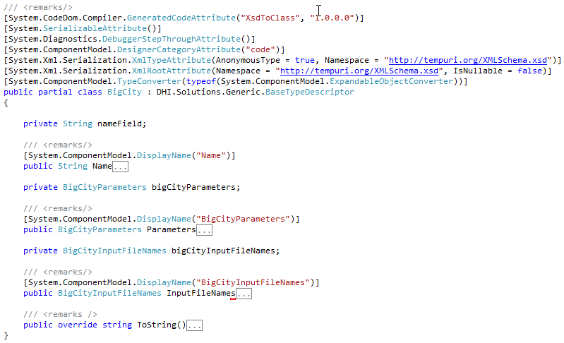
Listing 62 BigCity class - collapsed
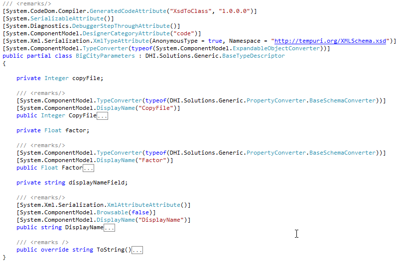
Listing 63 BigCityParameters class – collapsed
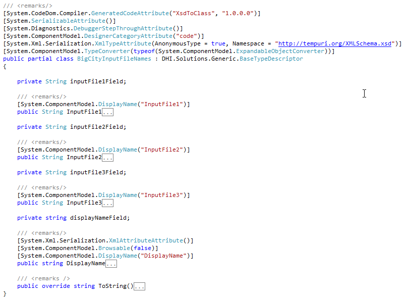
Listing 64 BigCityInputFileNames class - collapsed
Step 4 – store schema as resource
To distribute the XSD data with the adapter, include the xsd-files as resources in the adapter.
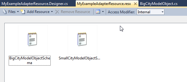
Figure 4: XSD files as resources in Visual Studio
Remember to update access modifier on the resources to public as described in section Add a resource file.
These xsd definitions are made available to the Platform via the public adapter method GetModelObjectSchema (see section Make GetModelObjectSchema method).
The use of the classes is shown in section _parseModel.
GIS data and symbology
The DSS assumes all GIS features to be in the same coordinate system or projection. This projection is returned in the IAdapterModelSetup.Projection property (a string). The projection string is expected to:-
-
Be in Well-Known-Text format as defined by the Open GIS Consortium, e.g. for UTM Zone 14N:
-
PROJCS["UTM_ZONE_14N", GEOGCS["World Geodetic System 72",
DATUM["WGS_72", SPHEROID["NWL_10D", 6378135, 298.26]],
PRIMEM["Greenwich", 0], UNIT["Meter", 1.0]],
PROJECTION["Traverse_Mercator"], PARAMETER["False_Easting", 500000.0],
PARAMETER["False_Northing", 0.0], PARAMETER["Central_Meridian", -99.0],
PARAMETER["Scale_Factor", 0.9996], PARAMETER["Latitude_of_origin", 0.0],
UNIT["Meter", 1.0] -
Be known among the projections in the MIKE OPERATIONS database. For PostgreSQL and PostGIS this means it must be present in the spatial_ref_sys table in the public schema (which is filled from the script in C:\Program Files (x86)\PostgreSQL\9.0\share\contrib\postgis-2.0\spatial_ref_sys.sql).
The feature details for each model object must all be in WKT and:-
-
express in valid coordinates either
-
POINT
-
LINESTRING
-
POLYGON
-
MULTIPOINT
-
MULTILINESTRING
-
MULTIPOLYGON
-
Share the same feature type for all model objects of the same type (as PostGIS cannot mix feature types in a layer).
If no projection or an invalid projection is supplied, the GIS information will simply be ignored during model registration. If a feature detail is invalid (in construction and/or values) the feature will not be constructed for the model setup during registration.
The adapter can provide the symbol to use in the Platform via the IAdapter.GetSymbology method which takes the model object type as argument. The Symbol specification is an XML document (string) which can look like the following:
\<FeatureLayerDefinition>
\<LayerStyleDefinition Color="Color [R=10,G=147,B=252]" OuterLineColor="Color [Black]" OuterLineThickness="1" OuterLineType="Solid" Size="6" SymbolType="Circle" />
\</FeatureLayerDefinition>"
The different attributes of the LayerDefinition is given by the GIS Manager, but examples are:
-
Polygon
-
Color, e.g "Color [R=211,G=255,B=190]"
-
OuterLineColor, e.g. "Color [Black]"
-
OuterLineThickness, e.g. "0.4"
-
OuterLineType, e.g. "Solid"
-
Line
-
Color, e.g. "Color [R=0,G=169,B=230]"
-
OuterLineColor, e.g. "Color [R=0,G=169,B=230]"
-
OuterLineThickness, e.g. "1"
-
OuterLineType, e.g. "Solid"
-
LineThickness, e.g. "1.2"
-
LineType, e.g. "Solid"
-
RoundCap, e.g. "True"
-
Point
-
Color, e.g. "Color [R=10,G=147,B=252]"
-
OuterLineColor, e.g. "Color [Black]"
-
OuterLineThickness, e.g. "1"
-
OuterLineType, e.g. "Solid"
-
Size, e.g. "6"
-
SymbolType, e.g. "Circle"
Alternatively, the point can take a bitmap as Symbol:
-
SymbolType= "Bitmap"
-
"SymbolBitmap, e.g. "iVBORw0KGgoAAAANSUhEUgAAAAwAAAAKCAYAAACALL/6AAAABGdBTUEAALGPC/xhBQAAAAlwSFlzAAAOwgAADsIBFShKgAAAAAd0SU1FB9sLBwkPKZTR8MgAAACKSURBVChTY/j//z8DKr79/1Mlw38GhvD/24AS6PKoit9V/W9SBCq2Yfj/bAbD/xgGhv9pEF1wdQgN+yz/GwMVNDRBFMPwEqBmBsv+/7ehtoE1bPACCgJNPoqkEFnTsyb5/6YMlv/7gbqAGhr/t4aimoqiGGrIq7Nz/vcDdQwbDfHA4GQgAlsCPQ0A+Ysq2titPU8AAAAASUVORK5CYII="
(which will display a small orange house).
Hint: to get the XML for a layer definition, try to create a layer in GIS Manager, select the layer in the legend and modify the layer details in the properties control and set the symbology as default (right-click menu on the legend). The script below will output the XML to the output window when run from the script debugger (drag/drop the feature class from the GIS Explorer to the parameter in the script to get the right path).
Listing 65 Sample symbology script
![Machine generated alternative text: DHI Solutions - workspacel — X Connection View Settings Properties D X k4) Start Page NewStoragel ___________________________ I ‘ X Burkina Faso - WaterUserNode - Feature Class Q. i GetDefauttSymbology I Feature Class [Çnge log entries Metadata rName Description Type Value type Value I ¿ IFeatureClass Entity descriptor — /Models and Scenari... I Name Burkina Faso - WaterUs j F]def GetDefan1tSymbo1ogy(featirc1as3) : Read Only False El Projection [] \<Script> I CoordinateSysteiWGS84 \<Author>Ander3 Klinting, DHI\</Author> E \<Description>Get the default layer syinbology XML\</Description> Name \<Parameters> The name of the feature class. \<Parameter naxne=”featureclass” t e=”IFeatreClass”>the featureciass\< ____________________ 9 \</Parameters> Prcperties j Tools Explorer io \</Script> . ll GIS DX 12 - Database:CBA_End:workspace1 13 print featureclass.Nar.e; - Models and Scenarios I print featureclass . DefaultSymbology 8 Burkina Faso ‘tt jJ Burkina Faso - Catchrnent r— E Burkina Faso - HydroPowerNode U Script Debugger X Burkina Faso- Reach rtch Output LSš!!Stack ______ --l BurkinaFaso-ReservoirNode _______________________________________________________________________________________ -- Burkina Faso- RiverNode Burkina Faso - WaterUserNode E Burkina Faso - laterUserNode atureLayerDefinition> \<IayerStyleDefinition Color=Color [R=230,G=152,B=O] OuterLineColor= Color I(!1 Lj Raster Database: CBA End:workspacel iTjieThickness= 1” OuterLineType= Solid Size=”12° SymbolType=’Bitmap’I__________________________ .itmap= “iVBOR«)KGgoAAAANSUhEUgA.8AAwAAAAKCAYAAACALL/6AA.MBGdBTU E (oi9Vf9SBCq2Vfj/bAbD/xgGh’9pEF1wdQgN+yz/GwMVNDRBFMPwEqBni _______________________________________ f7ehtoE1 G d 4 T ) A adrnin Connected to: CBA_End Status: Ready .:](../media/02f896c8995a2f0da2a18ae512b047da.png)
Machine generated alternative text: DHI Solutions - workspacel — X Connection View Settings Properties D X k4) Start Page NewStoragel ______ I ‘ X Burkina Faso - WaterUserNode - Feature Class Q. i GetDefauttSymbology I Feature Class [Çnge log entries Metadata rName Description Type Value type Value I ¿ IFeatureClass Entity descriptor — /Models and Scenari... I Name Burkina Faso - WaterUs j F]def GetDefan1tSymbo1ogy(featirc1as3) : Read Only False El Projection [] \<Script> I CoordinateSysteiWGS84 \<Author>Ander3 Klinting, DHI\</Author> E \<Description>Get the default layer syinbology XML\</Description> Name \<Parameters> The name of the feature class. \<Parameter naxne=”featureclass” t e=”IFeatreClass”>the featureciass\< _____ 9 \</Parameters> Prcperties j Tools Explorer io \</Script> . ll GIS DX 12 - Database:CBA_End:workspace1 13 print featureclass.Nar.e; - Models and Scenarios I print featureclass . DefaultSymbology 8 Burkina Faso ‘tt jJ Burkina Faso - Catchrnent r— E Burkina Faso - HydroPowerNode U Script Debugger X Burkina Faso- Reach rtch Output LSš!!Stack ___ --l BurkinaFaso-ReservoirNode ______________ -- Burkina Faso- RiverNode Burkina Faso - WaterUserNode E Burkina Faso - laterUserNode atureLayerDefinition> \<IayerStyleDefinition Color=Color [R=230,G=152,B=O] OuterLineColor= Color I(!1 Lj Raster Database: CBA End:workspacel iTjieThickness= 1” OuterLineType= Solid Size=”12° SymbolType=’Bitmap’I____ .itmap= “iVBOR«)KGgoAAAANSUhEUgA.8AAwAAAAKCAYAAACALL/6AA.MBGdBTU E (oi9Vf9SBCq2Vfj/bAbD/xgGh’9pEF1wdQgN+yz/GwMVNDRBFMPwEqBni _______ f7ehtoE1 G d 4 T ) A adrnin Connected to: CBA_End Status: Ready .:
Machine generated alternative text: DHI Solutions - workspacel — X Connection View Settings Properties D X k4) Start Page NewStoragel ______ I ‘ X Burkina Faso - WaterUserNode - Feature Class Q. i GetDefauttSymbology I Feature Class [Çnge log entries Metadata rName Description Type Value type Value I ¿ IFeatureClass Entity descriptor — /Models and Scenari... I Name Burkina Faso - WaterUs j F]def GetDefan1tSymbo1ogy(featirc1as3) : Read Only False El Projection [] \<Script> I CoordinateSysteiWGS84 \<Author>Ander3 Klinting, DHI\</Author> E \<Description>Get the default layer syinbology XML\</Description> Name \<Parameters> The name of the feature class. \<Parameter naxne=”featureclass” t e=”IFeatreClass”>the featureciass\< _____ 9 \</Parameters> Prcperties j Tools Explorer io \</Script> . ll GIS DX 12 - Database:CBA_End:workspace1 13 print featureclass.Nar.e; - Models and Scenarios I print featureclass . DefaultSymbology 8 Burkina Faso ‘tt jJ Burkina Faso - Catchrnent r— E Burkina Faso - HydroPowerNode U Script Debugger X Burkina Faso- Reach rtch Output LSš!!Stack ___ --l BurkinaFaso-ReservoirNode ______________ -- Burkina Faso- RiverNode Burkina Faso - WaterUserNode E Burkina Faso - laterUserNode atureLayerDefinition> \<IayerStyleDefinition Color=Color [R=230,G=152,B=O] OuterLineColor= Color I(!1 Lj Raster Database: CBA End:workspacel iTjieThickness= 1” OuterLineType= Solid Size=”12° SymbolType=’Bitmap’I____ .itmap= “iVBOR«)KGgoAAAANSUhEUgA.8AAwAAAAKCAYAAACALL/6AA.MBGdBTU E (oi9Vf9SBCq2Vfj/bAbD/xgGh’9pEF1wdQgN+yz/GwMVNDRBFMPwEqBni _______ f7ehtoE1 G d 4 T ) A adrnin Connected to: CBA_End Status: Ready .:
Figure 5: Example of running the GetDefaultSymbology script
Runtime.config
The MIKE OPERATIONS Platform is a highly configurable platform that can be extended in numerous ways – through custom made tools, views, explorers and job tasks. Although the platform can be used as an application on its own, its primary purpose is to serve as a framework for making specialised applications by adding custom tools, job tasks, views, explorers, modules and extensions to the Platform’s user interface shell.
All the functionality provided by the Platform comes as plugins. Plugins are much more than custom-made components, they are in fact carriers for all of the functionality that comes with the Platform or the application created on top of the Platform.
Plugins are loaded by the Platform based on their presence in the runtime.config configuration file which is located in the application’s installation folder. The only way to load it is to have it listed in the runtime.config file.
The overall structure of the runtime.config is depicted in Figure 6.
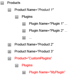
Figure 6: Runtime.config structure
Note the following from the figure:
-
Plugins are grouped in products where a product typically compares to a Platform manager as e.g. the Time series Manager
-
Each product can contain multiple plugins
-
Conventionally all plugins that do not belong to one of the standard managers, will be placed under the CustomPlugins product node – as shown by red text in Figure 6 above.
Each plugin is described through three parameters:
-
Name - should be the fully qualified name of the .NET class implementing the plugin
-
Type - defines the type of plugin. The value shall be the fully qualified name of the .NET interface that the plugin implements
-
Assembly - defines the assembly hosting the plugin. The value shall be the name of the assembly.
Table 7 below defines the possible basic plugin types.
Note: the interface specified as Type in the runtime.config plugin definition will match or inherit one of these entries.
| Plugin interface Type name | Description |
|---|---|
| DHI.Solutions.Generic.IDataViewControl | Designates a plugin that acts as a view |
| DHI.Solutions.Generic.IDTO | IDTO is strictly speaking not a plugin, but rather an identification of a class that holds mapping information between tables in the database and .NET classes |
| DHI.Solutions.Generic.IExplorerControl | Designates a plugin that shall act as an explorer |
| DHI.Solutions.Generic.IMenu | Designates a plugin that shall act as a menu |
| DHI.Solutions.Generic.IModule | Designates a plugin that shall act as a business layer module |
| DHI.Solutions.Generic.IPropertiesControl | Designates a plugin that shall act as a property control |
| DHI.Solutions.Generic.IShellExtension | Designates a plugin that shall act as a shell extension, i.e. extending the functionality of the Platform’s UI shell |
| DHI.Solutions.Generic.ITool | Designates a plugin that shall act as a tool |
| DHI.Solutions.Generic.IToolStrip | Designates a plugin that shall act as a tool strip |
Table 7: Plugin types