MIKE OPERATIONS Platform
Introduction
This document provides an overview of the MIKE OPERATIONS Platform (hereinafter Platform) architecture with focus on the main components, their interactions and the options the architecture provides for extensions and customisations.
The descriptions in the document are technical and make extensive use of UML components and sequence diagrams, therefore the reader should have some understanding of these types of diagrams.
The big picture
The Platform is a framework consisting of a large set of components and a set of rules and infrastructure plumbing code that makes it possible for software developers to combine these components to form solution implementations. Software developers can extend the set of components in various ways and therefore effectively tailor-make the system to suit the client’s specific requirements.
MIKE OPERATIONS Components are the set of components that are maintained by DHI and made available with the option of a service and maintenance contract. In contrast to these components, are those that are tailor-made within solution-finding projects and these components are typically used only in a specific solution.
Figure 1 below depicts the organisation of these components within the Platform.
Figure 1: Component organisation
It can be seen from Figure 1 that the Platform includes several types of components – ranging from complete modules, overviews, explorers to tools. This document will discuss in detail, the differences between the types of components, how the framework hosts or supports such components and how they interact.
Is the Platform then a component library or an application? - It is in fact both.
-
It is an application in the sense that the Platform comes with a program that can load all of the MIKE OPERATIONS components as well as the tailor-made ones and therefore provides the user with a wide set of features. This application is more a reference application than an application that truly serves specific needs.
-
It is a component library in the sense that it provides possibilities for combining the components and hosting tailor-made software in such a way that the final product appears as a solution tailored for a set of specific use cases.
The DSS Solution
From a strictly top-down perspective a DSS solution can be depicted as a system consisting of 3 different parts – business intelligence, modelling and data. Their interaction with each other is illustrated in Figure 2.
Figure 2: The 3 main parts of a DSS solution
The business intelligence part is a Windows application providing the clients with a functionality that addresses their specific requirements. As the above figure depicts, the users interact with the system through the business intelligence part, constructed as leverage to the platform.
The modelling part consists of one or more modelling tools that are integrated with the business intelligence part through an adapter. Modelling tools can be DHI proprietary tools such as MIKE 11 or MIKE BASIN, but they could also be public domain Model tools or the proprietary Model tools of another company.
The business intelligence and modelling parts usually reside in different processes and often also on different computers, implying that a client-server relation exists between these two parts.
The data part is a traditional RDBMS system that stores all the data that both the business intelligence and the modelling parts operate upon.
In the remaining part of this document, the focus is on the architecture of the business intelligence part, i.e. the Platform.
The Application and Shell components
The main starting point of interaction with the Platform for most users will be through the business intelligence part. This includes two main components – the Shell and the Application which are hosting containers for the user interface components and the functionality components respectively.
The interaction between the Application and the Shell components is depicted in Figure 3. Note that the components are defined through their public interfaces IShell and IApplication.
Figure 3: Shell and Application components
The business intelligence part follows strict component-based design patterns by supporting the separation of concerns with a number of high-level modules taking care of specific well-defined functionality areas. Each of these high-level modules follows the N-layer design pattern being, a distinct data layer, a business layer and a user interface layer.
An example of such a high-level module is the Time series Manager. The Time series Manager includes the functionality for reading and writing time series, processing time series and displaying and editing time series data.
The Application component
The Application component provides access to the business functionality within the Platform through hosting all the loaded modules and tools. Modules and tools are the only two functionality bearing components provided by the Platform.
The relation between these two components and the Application component is shown in Figure 4 and will be discussed later in this section.
Figure 4: Application, Module and Tool components
When loaded, the Application component scans a configuration file – typically named runtime.config – for dynamically loadable components or in short, plugins. A plugin is a component that implements the IPlugin interface which is the case for modules and a module implements the IModule interface, which in turn inherits from IPlugin. The Application component not only detects the modules, but also instantiates them and makes them available for programmatic access through a Modules property.
The loading mechanism is depicted in the sequence diagram provided Figure 5.
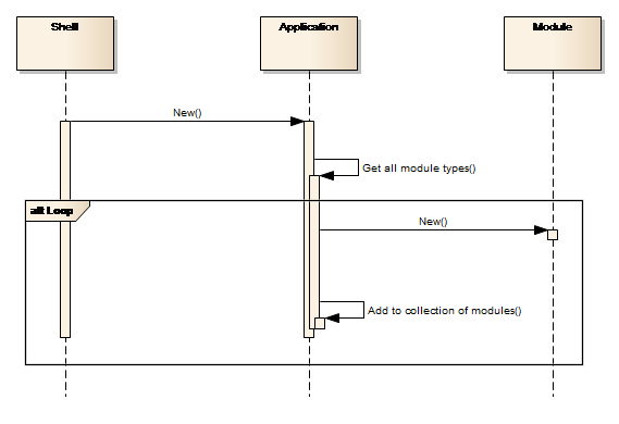
Figure 5: Discovering and enabling Modules
For more details on the modules, refer to the section on Module components later in this document.
The other functionality bearing components are the tool components. These are, in comparison with the modules, more lightweight, with much more limited and specific functionality. An example of a tool component is the Standard Deviation tool which provides functionality for calculating the standard deviation of a time series.
Tools components are also hosted by the Application component.
All tools implement the ITool interface and are identified and instantiated by the Application component, similar to the Module components. Tools are discussed in more detail in the
Tool components section.
Table 1 below summarises the mentioned interfaces.
| Interface | Description |
|---|---|
| IApplication | Interface providing access to the Application members (including IModules and ITools). |
| IModules | A collection of all modules listed in the loaded runtime configuration file. |
| ITools | A collection of all tools listed in the loaded runtime configuration file. |
| IModule | The interface each module must implement in order to be identified as a module |
| ITool | The interface each tool must implement in order to be identified as a tool. The interface provides information about on which object types the tool can execute and contains methods for defining input, executing the tool and delivering output. |
| IModuleName, e.g. ITimeseries | Interface providing the business functionality of a specific module component, ModuleName. |
| IPlugin | Interface that must be implemented by all types of plugins. |
Table : Application component interfaces
The Shell component
The Shell component hosts and displays all the user interface components, consisting of two basic types:
-
Explorer windows
-
Data view windows
The windows explorer serves as the entrance point to explore the relevant data for a particular module, while the data views are used for presenting the data. These typically include standard user interface controls such as charts or tables.
Each plugable user interface component implements either the IExplorerControl or IDataViewControl interface which inherits from IPlugin. Their relation to the Shell component is shown in Figure 6.
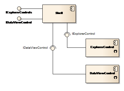
Figure 6: Shell, Explorer and Data view components
Components that implement both IExplorerControl and are listed in the applications runtime configuration file, will be loaded and instantiated by the Shell component while the application is being started. This process is identical to the way the Application component loads modules and tools. The Shell components make the explorers and data views available through two public properties, ExplorerControls and DataViewControls.
Components implementing IDataViewControl are detected, instantiated and made available following the same pattern.
Table 2 below summarises the mentioned interfaces.
| Interface | Description |
|---|---|
| IShell | Interface provided by the shell component including the IExplorerControls and IDataViewControls interfaces |
| IExplorerControls | A collection of all explorers listed in the loaded runtime configuration file. |
| IExplorerControl | The interface that each explorer shall implement in order to be identified as an explorer |
| IDataViewControls | A collection of all data views listed in the loaded runtime configuration file. |
| IDataViewControl | The interface that each data view shall implement in order to be identified as a data view |
Table : Important user interface interfaces
Business functionality
Business functionality, i.e. functionality that directly relates to the domain of the solution, is provided through two types of components – modules and tools. These two types are discussed in more detail in the following two sections.
Module components
A module component implements specific functionality and is useful in its own right. Typically, a module component implements functionality with regard to a well-defined category of data. For example, the Time series Manager module handles functionality with regard to time series and the Scenario Manager handles functionality pertaining to scenarios and simulations.
The business logic of a module is exposed via an API. If and when a module needs functionality provided by another module, access to this functionality is achieved through the other module’s API.
Each of the individual module components uses a three-layered architecture, presentation (user interface), business logic and data access. This is shown conceptually in Figure 7 below. A layered architecture has a number of benefits. The application becomes easier to test, adding new functionality becomes easier and other applications will be able to re-use functionality exposed by the layers. The latter has been a key design goal for the Platform.
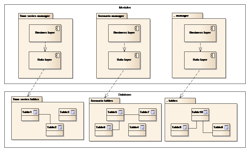
Figure 7: Module architecture
Note the following in the figure above:
-
Each module is responsible for a part of the full data model. E.g. the Time series Manager handles the time series part of the full data model. If other modules need access to time series data, they will interact with the Time series Manager.
-
The data model provides full database managed relationships, i.e. an entity belonging to one part of the data model can be used as a foreign key in another part. (The separation shown at the Database layer in the figure is conceptual).
This is a strictly layered architecture, meaning that each layer interacts with only the layers directly below and above itself. Below follows a short description of the responsibilities of the two layers:
Business layer
The business layer implements the IModule interface and furthermore provides the business functionality of the module itself through the IModuleName interface (ex. ITimeSeries).
Data Layer
The data layer is responsible for creating, reading, updating and deleting data for a particular module.
Tool components
Tools target specific functionality areas such as time series or GIS tools. From a software architectural perspective, Tool components are “cross cutting” components that are not associated with a particular module, but can be used by any module. Tool components are normally lightweight, with much more limited and specific functionality than in the case of modules.
All tools require some specific input data, have an execute method and deliver some output. For example, the time series Resample tool expects a time series as input and delivers a re-sampled time series as output. Each tool implements the ITool interface and similar to the module, is registered for use when the Solution is started.
The toolbox uses the .NET reflection mechanism to establish knowledge of the types of data that the individual tool consumes and produces. This makes it possible to build sequences of tool executions where the output from one tool is automatically made available as an input for the next tool in the sequence. The toolbox will include specialized tools for displaying and handling output.
This architecture provides a mechanism for developing custom tools catering to specific needs within an organisation or a project, while being seamlessly integrated with the Platform.
User interface components
The user interface components are organized according to the modules they mainly serve, e.g. Explorers and Data Views for the Time series Manager, Explorers and Data Views for the GIS Manager, etc. These components also collaborate on the module level in order to provide coherent end-to-end functionality for the benefits of the users. For example, the Time series Explorer makes use of both the Time series Manager module and the GIS Manager module for associating time series with GIS features. Similarly, whilst creating a new scenario, the Scenario Manager will use the business functionality from both the Scenario Manager module and the Time series Manager module to provide the user with a list of relevant input time series to choose from.
The use of modules from the User Interface layer is depicted in Figure 8 below.
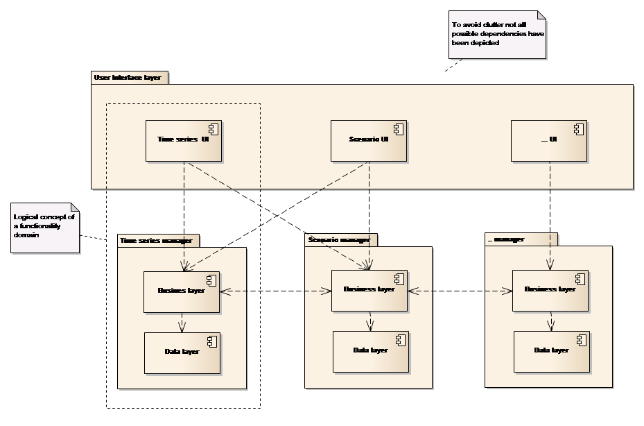
Figure 8: User interface components and modules
Note from the figure that:-
-
The combination of a specific module and its primary related user interface components – explorers and data views, is defined as a functionality domain (hereafter referred to as domain). For example, the Time series domain constitutes the Time series Manager module and the corresponding Time series user interface components
-
All user interface components can make use of all modules
-
User interface components can interact across managers.
There is a slight difference between interactions within the boundary of a manager and the interactions that occur between managers. The former happens through direct component references, while the latter occurs through a factory mechanism. This is depicted in Figure 9.
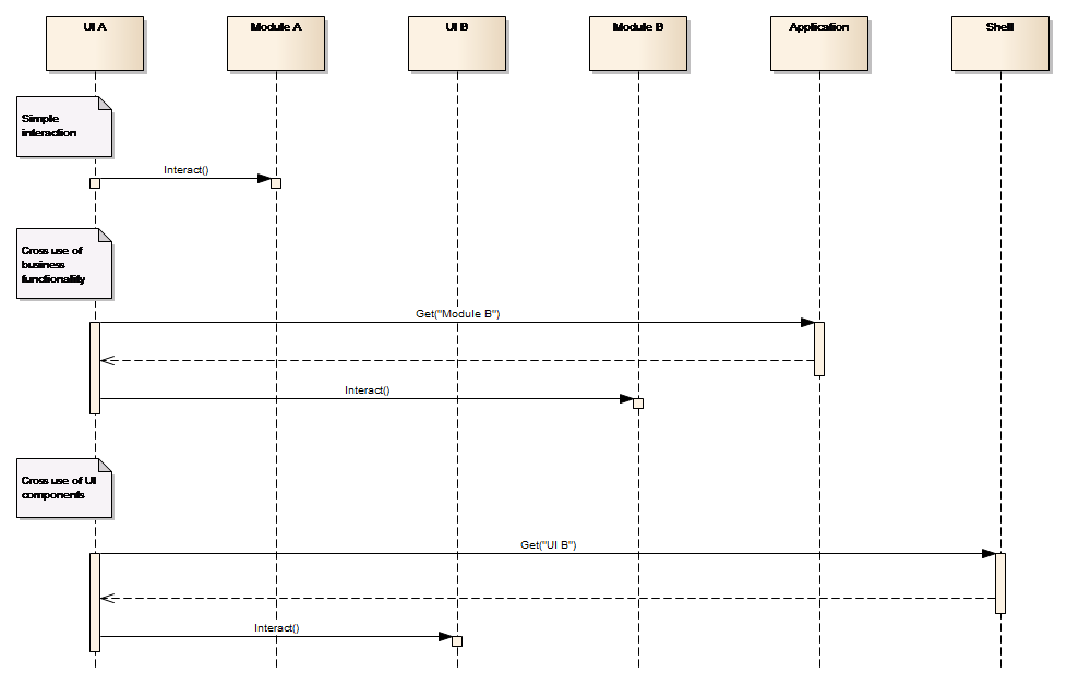
Figure 9: Cross manager component referencing
Note from the figure that:-
-
A user interface component can directly interact with the module within its own domain, but when interacting with a module in another domain, it will use the Application component as factory. This provides for a loosely coupled system.
-
User interface components from different domains can also make use of each other through a factory mechanism, e.g. a Time series user interface component, when interacting with a GIS user interface component will use the Shell as a factory for getting a reference to the object implementing a specified interface. This makes a loosely coupled system coherent.
-
All object definitions occur through interfaces defined at a generic level whereby all domains know the interface for all business objects (the module APIs). The loose coupling allows for different user interface components as well as scripting, using the business object at module level.
-
All module interfaces are defined at a generic level and are therefore available across domains. The loose coupling allows for different user interface components as well as scripting, to access modules in all domains.
| Interface | Description |
|---|---|
| IRuntimeAdapter | Interface with methods for executing the Model Tool: For preparing the model setup by converting input time series into model tool proprietary format, prepare initial conditions into model tool format and alter model tool setup with respect to simulation period setting. For executing and controlling the model tool and verifying success For retrieving outputs from the model tool proprietary format to be returned to the DSS. |
| IConfigAdapter | Interface with methods for retrieving the necessary information for establishing a DSS model setup: Parsing a model setup (by files or by using an API, if available) to retrieve all relevant configuration data to be used by the DSS: input time series, initial conditions, potential output time series and other output data, log files Returning all data required for enabling re-store of the model setup for later editing and execution to the Platform Restoring model setup to the form required to edit the content with the Model tool. |
| IModelSetup | The data structure representing a model setup in the NB DSS. It includes properties for: Exchanging initial conditions to/from the model Input time series Model objects Output time series. |
Table : Model scenario important interfaces
Extensions
Most projects applying the Platform to establish a client specific solution will need to customize the look and feel and extend the functionality that comes with the “out of the box” installation. This is done in addition to populating the solution with data and integrating it with the client’s existing IT/IS infrastructure.
In many projects it will suffice to use the built-in scripting functionality for adding the required project specific functionality and the user interface options provided by the standard Spreadsheet Manager for constructing simple data entries and presentation screens. These two components can be combined through the spreadsheet component executing scripts as standard spreadsheet functions and also have scripts executed as a function of user interface actions. These are the only options for extending the Platform.
An implementing project can add user interface elements to the raw Platform in two different ways:
-
Through the Platform’s visualizer concept where a visualizer is a custom functionality that can be accessed from the different entity Explorer’s context menu. The Platform will scan for visualizers that can consume the selected type of entity whilst building the context menu. In this way it will be possible for a solution to have very specific time series functionality or visualisation attached to the standard time series context menu.
-
It is simple for a project to implement a visualizer, as all it takes is any .NET class to implement the Platform’s IVisualizer interface. This interface is very basic with just two properties, a description field and a list of supported data types.
-
Through the Platform’s shell extension mechanism which provides an option for tailor-made components to be called while the application loads. This component typically, but not limited to, displays data views.
With regard to Business functionality, a solution project can extend the Platform to tailor-made tools and modules as previously described. Tools can be executed from the Platform’s toolbox, scripts or spreadsheet, while a new module typically requires some supporting user interface. This can be formulated through visualizers and/or a shell extension.
It is also possible for a solution project to add complete new managers and integrate them with the standard Platform components through registering them with the runtime configuration file.
Data and the Database
The Platform stores all data within a standard related database system including time series, GIS (spatial), model scenarios, etc. The next section describes the basic principles that govern the data models used by the Platform.
Data entities
Time series, GIS features and scenarios are likely data types that many users will frequently require when working with a Platform based solution. These are however, just a few of the numerous different types of data that are supported by the Platform in its default configuration. Other types include spreadsheets, scripts, documents, GIS raster, indicators and meta-data to which solution implementing projects can add their own data types.
It is important to note that the individual modules are responsible for handling their own well-defined data types. For example, the Time series Manager component handles all time series data and the Scenario Manager component handles all scenario data. This means that if the Scenario Manager for example, has to retrieve time series values and wants to run a scenario simulation, it cannot retrieve data directly from the database, but has to request the business services of the Time series Manager to retrieve such data, as is illustrated in Figure 10.
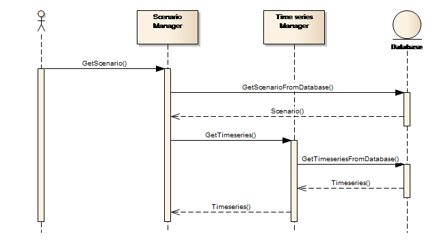
Figure 10: Accessing data from another module
The next 4 sections contain examples that explain how the platform manages the storage of GIS features, time series, model scenarios and meta-data.
GIS Features
GIS data is a collection of feature classes, e.g. countries, cities and rivers, with each feature being characterized by an attribute of type geometry. In the database, the geometry attribute are handled by an OGC-compliant geometry data type.
Feature classes are stored in the database as database tables, i.e. one physical table per feature class. This is similar to most other GIS systems storing data in relational databases. Figure 11 illustrates this table layout.
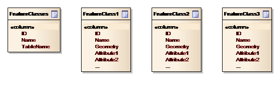
Figure 11: Conceptual data model for GIS features
In order to facilitate querying the available feature classes or feature classes of specific types, the GIS module includes a table – feature_class - that stores feature class meta-data. This includes the feature class name, the name of the corresponding table and others.
Time series
Time series data are separated into time series descriptions in the Timeseries table and the actual data in the TimeseriesValues table. The conceptual data model is depicted in Figure 12 below.
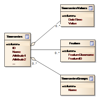
Figure 12: Conceptual data model for Time series
Note from the figure that:-
-
A time series can be associated with one or more features, i.e. linked to GIS entities
-
A time series can be grouped together and thereby support ensembles of time series.
Time series data need special consideration and solutions compared to other data, because of the potentially large amounts of data. This implies that time series values – as opposed to the time series properties - have to be “lazy loaded”, which means they are only read from the database when they are needed for visualization or processing.
Model scenarios
Scenarios represent the link between a model setup and the input and output data involved in model execution. Scenarios have reference to a model setup and to one or more time series and time series groups
Figure 13 depicts the conceptual data model for Scenarios.
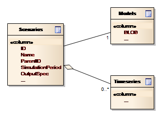
Figure 13: Conceptual data model for Scenarios
Note from the figure that:-
-
The ParentId attribute in the Scenarios entity allows the user interface to display scenarios, or rather their names, in a hierarchical manner.
-
The scenario is associated with a model, i.e. the entity holding the model setup data
-
The scenario can be associated with time series
-
The lower compartment of the scenario entity contains specific scenario settings.
Meta-data
Meta data exists for almost all of the entities in the system. A common component exists for managing the Meta data on behalf of the other components, thus connecting Meta data to entities via a central Entity table.
Meta data consists of a list of key-value pairs associated with an entity. The key is defined in the Meta data system itself, to allow for a consistent and language independent terminology across the system. The values are retained as XML strings, adhering to module specific schemas. The conceptual data model for the definition section of the Meta data system is shown in Figure 14.
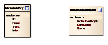
Figure 14: Conceptual data model for Meta data definition
Workspaces
The Platform supports the organization of data in distinct workspaces, e.g. having data for different studies separated in isolated areas of the database. A workspace within the Platform corresponds to a database schema – i.e. a container for a set of database tables and other database objects. A workspace is therefore a database schema that includes all tables, except a few system-oriented ones. This is depicted in Figure 15 below.
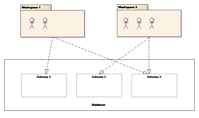
Figure 15: Schemas and workspaces
Note from the figure that:-
-
Users that are not associated with a workspace will not be able to log on to the solution
-
Users that are associated with a workspace; i.e. have selected a workspace when logging on to the solution, will have access to the database schema associated with the workspace.
One workspace is a single security realm. In other words, the user John is treated differently when logging onto different workspaces. John can have one profile in workspace “A” and another in workspace “B”.
Data Access Pattern
The communication between the Platform and the database is achieved by individual modules in a data access layer, using the well-known Data Access Object (DAO) pattern. In this pattern, a DAO component defines an interface to the persistence operations – Create, Read, Update and Delete in short CRUD, as related to a particular entity.
The data access layer of each module includes a number of DAO components implementing the generic interface IDAO\<Entity>, each handling the CRUD operation for a particular entity.
In addition to the methods in the IDAO\<Entity> interface, each DAO component can implement additional methods in a DAO-specific interface (IEntityNameDAO).
Each entity component implements the IEntity interface. Furthermore, these components provide all the properties of the particular entity in the entity-specific interface IEntityName. See Figure 16.
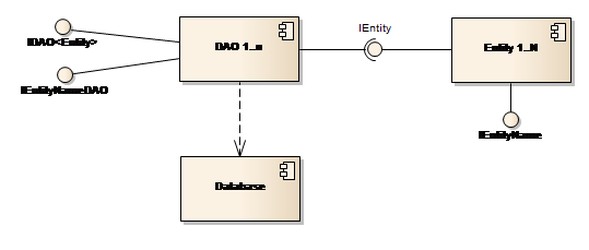
Figure 16: Data access through the DAO pattern
Table 4 below summarises the mentioned interfaces.
| Interface | Description |
|---|---|
| IEntity | Interface that is implemented by all Entity components. Including at least, an ID property of type GUID. |
| IEntityName (e.g. IDataSeries) | Entity-specific interface with all the properties of that particular entity. |
| IDAO\<Entity> | A generic interface that all DAO components implement. The interface comprises methods such as Create, Get, GetAll, Update and Delete for handling the basic CRUD operations for a particular Entity component. |
Table : DAO-related interfaces
Modelling programs
This section describes the Model tool component and its interaction with the Platform. Model tools are “off-the-shelf” software products, typically simulation software, integrated with the Platform using the well-known Adapter pattern.
Most modelling tools and certainly the DHI MIKE model tools, have both a user interface component and an engine component. The engine controls the model execution, i.e. solving the mathematical equations and processes, while the user interface is used for configuring the model or creating the model setup.
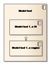
Figure 17: The Model tools
The following section describes the use of model adapters. The description is generic and not biased towards the MIKE modelling tools.
The Model Adapters
Interaction between the Platform and the Model Tools is achieved by using the Adapter design pattern. Each Model Tool component includes a specific model adapter component that implements two interfaces: IConfigAdapter controlling the model setup registration and IRuntimeAdapter controlling the preparation and execution of a model simulation (see Figure 18).
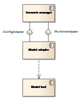
Figure 18: The model adapters
Model Setup Registration
Model setup registration in the Platform is performed by using the IConfigAdapter interface of the model adapter as shown in Figure 19.
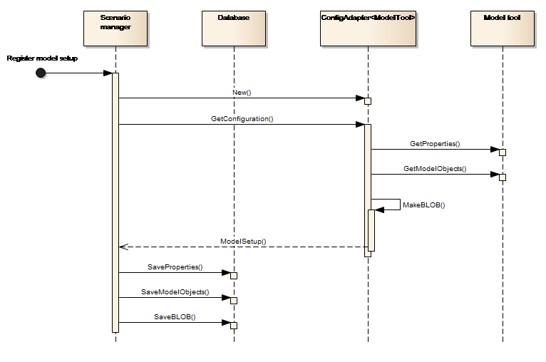
Figure 19: Register model setup
In this sequence:-
-
The Platform component (the Scenario Manager) launches the model adapter
-
The model adapter communicates with the Model tool, to interpret the model setup and return a data structure with the model setup information to the Scenario Manager.
-
The Scenario Manager stores the Model setup in the database.
The Model setup returned from the adapter is a data structure representing the model setup in the Platform. This data structure will be defined in an interface (IModelSetup) and will consist of the following groups of data:
-
BLOB - a binary representation of the full model setup in the database. This is used to re-create the model setup when editing or running it with the Model Tools.
-
Properties. These are the definition in the database allowing the system to run a Model Setup. They include:
-
Base data such as name, Model Tool reference, description etc.
-
A set of time series data or parameters required to run a simulation. This data will be stored explicitly in the data base. For instance:
-
Model input and output time-series.
-
Parameters such as start and end of simulation.
-
References to the log-file for examining the Model Tool performance.
-
-
Model objects - are model setup features such as hydraulic structures, catchments and river reaches.
The Model setup registration in the Platform is depicted as data flow in
Figure 20 below.
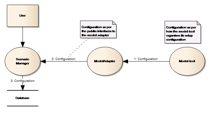
Figure 20: Data flow when registering a model
Note from the figure:-
-
the flow from the Model tool to the Model adapter is based on an agreement between the two components
-
the flow from the Model Adapter to the Scenario Manager is based on the public IConfigAdapter interface, which uses the Model setup data structure to exchange model configuration information.
The type of interaction between the model adapter and the model tool, i.e. how the information is exchanged between the model adapter and the model tool, depends mainly on the capabilities of the model tool. If the model tool provides an API for getting and setting properties of a model, then the model adapter will probably make use of such an API. In the case where a model tool does not provide such an API, the Model tool will have to directly process the input files constituting the model, e.g. through text processing.
When registering a model, the user will be presented with a Model registration wizard. This wizard will guide the user through the registration process which incorporates the selection of the model tool, selection of input file(s) constituting the model, either by browsing the file system or communicating through the model tool and finally mapping between input time series and GIS features.
Scenario Simulation
Execution of a scenario simulation in the NB DSS involves preparing a model setup for simulation, executing the Model tool and extracting selected simulation outputs to be stored in the database. This is done using the IRuntimeAdapter interface of the model adapter as illustrated in Figure 21.
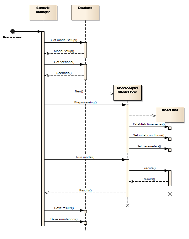
Figure 21: Run scenario
The figure shows that:-
-
The Platform (Scenario Manager) retrieves the model setup and the variations to the model setup (DSS scenario) from the database.
-
The Model adapter establishes the model setup (unpacking the BLOB and establishing a directory structure for the model tool and adapter to work in), on behalf of the Scenario Manager, assuming that the model tool is file based and exchange of data via the adapter is done at file level. This occurs when the Scenario Manager launches the model adapter with the selected scenario and calls the Preprocessing() method on the adapter.
-
The model adapter understands how to establish the input time series, the initial conditions and the input-parameters of the variations (the scenario) in the simulation folder.
-
The adapter knows how to execute the Model tool.
-
The adapter knows how to retrieve simulation results from the Model tool.
The execution of a scenario within the NB DSS is depicted as a data flow in Figure 22.
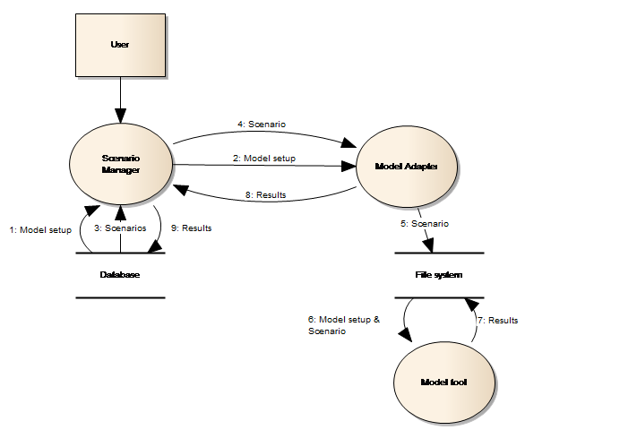
Figure 22: Run scenario data flow
Note from the figure that:-
-
The flow from the Scenario Manager to the file system goes through the Model Adapter, i.e. the Platform does not interact with the file system directly. Communication comprises the unpacking of a BLOB containing the model configuration which is loaded from the Database to the file system folder.
-
The flow from the Model Adapter to the file system follows the custom agreement between the Model Adapter and the Model tool
-
The flow from the Scenario Manager to the Model Adapter uses the public IRuntimeAdapter interface.
Linking of models
The Platform supports dynamic linking on a time step by time step basis - of models through the adapter pattern. A dynamically linked model is one that makes use of two or more model tools that exchange data during the simulation. This is in contrast to sequentially linked models, where one model tool simulation provides the input for the next model tool simulation.
Seen from the Platform perspective, there is no difference between a dynamically linked model and a “single” model. In both these cases, an adapter that the Platform can use in order to read and write model setups, run simulations etc, must exist.
Model simulations
The Platform supports different types of simulations. All of these are well supported through the adapter approach:
-
Optimisation – The IConfigAdapter interface of the model adapter provides methods that the NB BSS system can use in order to obtain the list of parameters that can be used in order to perform optimization.
-
Ensembles – The IRuntimeAdapter interface of the model adapter provides optional methods that the Platform can use for optimizing the performance of the whole system while running an ensemble-based simulation. For example, limiting the system overhead by restoring models to the file system.
-
Linked models – From the Platform’s perspective, this is merely the execution of models in sequence, i.e. the role of the adapter is no different from the standard case.
-
Rule-based simulation (e.g. controlling the simulation from a script) – The Platform scripting interface provides methods for restoring models stored in the database to the file system and launching model simulations. I.e. the adapter approach does not negatively affect rule-based simulation.
Data security
The Platform is used in many different solutions and caters for users requiring different roles in the respective solutions. Users will access the system for various purposes and actions, which requires support to assign different user permissions for data access.
In this respect the Platform can be characterised as:-
-
Being simple to administer
-
Providing user access to the data that is required for a specific purpose
-
Allowing sharing of data across installations
-
Supporting organising data in distinct workspaces.
Workspace user roles
Workspaces support three different types of user roles:
-
Reviewer – a reviewer has the permission to view all data within the workspace
-
Member – a member can manipulate all data within the study
-
Lead – lead can administer users within the workspace.
Scripting batch processing
The User interface is not the only way a user can interact with the Platform; the latter includes comprehensive scripting capabilities through an embedded Python development environment.
All functionalities provided by the business service layers, are based on documented public interfaces which make it possible to programmatically access the business services and thereby automate interactions with the system. Scripting therefore becomes another way to interact with the solution, when compared with the User interface. Strictly speaking, model tools are components outside the Platform. They can also be accessed from the Platform’s scripting component, if they provide a programmatic interface.
Figure 23 below is the key to understanding how scripting is implemented within the Platform.
Figure 23: Application, Modules and Tools
The Application component glues all the other components (Modules and Tools) together to form a single solution. The Application component itself does not provide any user interface; this is deferred to the Shell component. See the discussion in the The Application and Shell components section.
When a user wants to write script within the Platform, the Application component provides the root of the object model (the entry point to the business functionality). Access to Modules and Tools is provided through the Application object. The text box below shows a sample script that retrieves a time series from the database and uses a standard ITool-based tool for resampling it.
Listing Sample Python script that interacts with the Platform business layer
Note how the script at point (1) gets a reference to the Time series module through the Application object – the global app variable. At point (2) the script reads a time series from the database. The script uses a standard Tool at point (5). The final part of the script is extracting the result value from the tool output (4) and returning it to the caller (point 5).
The Platform includes the required development tools like editor and debugger for coding scripts. A number of the standard modules in the Platform provide extension points to which the user can associate scripts. For example, the Scenario Manager makes it possible to use scripts as input time series and thereby supports flexible scenario simulation options.
Microsoft’s Dynamic Language Runtime (DLR) technology is the foundation on which the Platform and Python integration has been established. The implementation is based on hosting the Microsoft ScriptEngine component and providing a development environment for Python coding.
Batch processing
The Platform supports batch processing through a dedicated functionality component named Job Manager which makes it possible not only to create batches of tasks and have them executed as a single unit, but also to schedule such an execution at a given point in time, repeatedly and on different computers. In other words, it is possible to establish proper simulation servers that handle all scheduled batch executions.
Batch execution is based on the concept that a job is a list of individual tasks. The Job Manager provides a user interface where one can declaratively compose a job from a large number of task elements that represent the business functionality provided by the Platform.
Each task is graphically customised for working with specific entities and according to task specific properties. Examples of such tasks are ImportTimeseries, CopyTimeseries, FilterTimeseries, RunScenario, ApproveSimulation and PublishEvent, amongst others.
Figure 24 depicts the user interface used for composing a job.
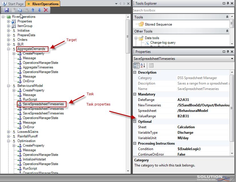
Figure 24: Job editing
It can be noted from the above figure that a job consists of different sections named targets, where each target consists of one or more tasks. One target can depend on other targets, tasks can be conditionally executed and task execution can stop at first error or it can continue despite errors. A target can include an error task which will be called in case other tasks within the same target return with an error.
The base technology behind the job implementation is Microsoft’s BuildEngine component which can be defined as a lightweight workflow engine. Microsoft uses the same component as part of their MSBuild technology that is used by, for example Visual Studio for building software projects. The BuildEngine takes the job as input – after having been transformed into an XML structure and executes the user’s selected targets.
It is very simple to extend the Platform with tailor-made tasks. It simply requires a .NET class that inherits from the DssTaskBase class, which only requires implementation of a single method - Execute().
Installation and deployment
Deployment of a solution based on the Platform can take place in a number of different configurations, ranging from installing the software on a single computer, to distributing it over a number of computers.
The platform in its baseline is designed as a traditional 2-layered system, as illustrated in Figure 25.
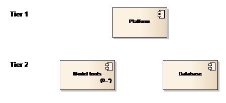
Figure 25: Overall decomposition
The Platform holds all the DSS processing functionality, e.g. time series management and scenario management and is installed on tier 1. Tier 2 hosts the database and the model tools.
One computer deployment
The simplest possible deployment model is having the three main parts of the Solution installed on the same computer as depicted in Figure 26.
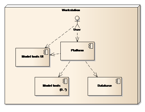
Figure 26: One computer deployment
The primary aim of this deployment model is to service organisations or individuals with limited requirements or one person only, working with the Solution. The primary limitations of this type of deployment are:
-
Only one person can work with the Solution at any given time.
-
It requires model tools to be installed locally.
Two computer deployment
Organisations that have substantial needs or groups of people that need to share data can opt for a two computer deployment model as shown in Figure 27 below.
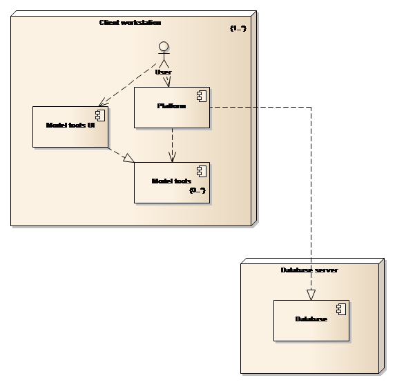
Figure 27: Two computer deployment model
It can be seen from the figure above that the deployed components are the same as for the one computer deployment model, but with the database being installed on a dedicated computer. This model will allow concurrent user access to the database and thereby lend support to project teams. Model tools are still installed on the computer hosting the user interface, which may or may not, be problematic with respect to license management and the efficient utilisation of licenses.
Three computer deployment
The final deployment model distributes the three parts on three different computers as shown in Figure 28.
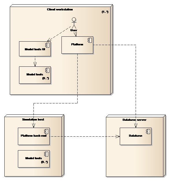
Figure 28: Three computer deployment model
This type of deployment model leverages the Platform’s built-in functionality for remote and scheduled execution.
Note that the Platform back-end component is a stripped down version of the full Platform where the user interface components typically are left out of the deployment.